The primary assembly of a type certificated aircraft is normally performed by the manufacturer at the factory. The assembly includes putting together the major components, such as the fuselage, empennage, wing sections, nacelles, landing gear, and installing the powerplant. Attached to the wing and empennage are primary flight control surfaces including ailerons, elevators, and rudder. Additionally, installation of auxiliary flight control surfaces may include wing flaps, spoilers, speed brakes, slats, and leading edge flaps.
The assembly of other aircraft outside of a manufacturer’s facility is usually limited to smaller size and experimental amateur-built aircraft. Typically, after a major overhaul, repair, or alteration, the reassembly of an aircraft may include reattaching wings to the fuselage, balancing of and installation of flight control surfaces, installation of the landing gear, and installation of the powerplant(s).
Any time repairs on a control surface add weight fore or aft of the hinge center line, the control surface must be rebalanced. When an aircraft is repainted, the balance of the control surfaces must be checked. Any control surface that is out of balance is unstable and does not remain in a streamlined position during normal flight. For example, an aileron that is trailing-edge heavy moves down when the wing deflects upward, and up when the wing deflects downward. Such a condition can cause unexpected and violent maneuvers of the aircraft. In extreme cases, fluttering and buffeting may develop to a degree that could cause the complete loss of the aircraft.
Rebalancing a control surface concerns both static and dynamic balance. A control surface that is statically balanced is also dynamically balanced.
When a control surface is mounted on a balance stand, a downward travel of the trailing edge below the horizontal position indicates underbalance. Some manufacturers indicate this condition with a plus (+) sign. An upward movement of the trailing edge, above the horizontal position indicates overbalance. This is designated by a minus (–) sign. These signs show the need for more or less weight in the correct area to achieve a balanced control surface, as shown in Figure 1.
The assembly of other aircraft outside of a manufacturer’s facility is usually limited to smaller size and experimental amateur-built aircraft. Typically, after a major overhaul, repair, or alteration, the reassembly of an aircraft may include reattaching wings to the fuselage, balancing of and installation of flight control surfaces, installation of the landing gear, and installation of the powerplant(s).
Rebalancing of Aircraft Control Surfaces
This article is presented for familiarization purposes only. Explicit instructions for the balancing of control surfaces are given in the manufacturer’s service and overhaul manuals for the specific aircraft and must be followed closely.Any time repairs on a control surface add weight fore or aft of the hinge center line, the control surface must be rebalanced. When an aircraft is repainted, the balance of the control surfaces must be checked. Any control surface that is out of balance is unstable and does not remain in a streamlined position during normal flight. For example, an aileron that is trailing-edge heavy moves down when the wing deflects upward, and up when the wing deflects downward. Such a condition can cause unexpected and violent maneuvers of the aircraft. In extreme cases, fluttering and buffeting may develop to a degree that could cause the complete loss of the aircraft.
Rebalancing a control surface concerns both static and dynamic balance. A control surface that is statically balanced is also dynamically balanced.
Static Balance
Static balance is the tendency of an object to remain stationary when supported from its own CG. There are two ways in which a control surface may be out of static balance. They are called underbalance and overbalance.When a control surface is mounted on a balance stand, a downward travel of the trailing edge below the horizontal position indicates underbalance. Some manufacturers indicate this condition with a plus (+) sign. An upward movement of the trailing edge, above the horizontal position indicates overbalance. This is designated by a minus (–) sign. These signs show the need for more or less weight in the correct area to achieve a balanced control surface, as shown in Figure 1.
 |
| Figure 1. Control surface static balance |
A tail-heavy condition (static underbalance) causes undesirable flight performance and is not usually allowed. Better flight operations are gained by nose-heavy static overbalance. Most manufacturers advocate the existence of nose-heavy control surfaces.
Dynamic Balance
Dynamic balance is that condition in a rotating body wherein all rotating forces are balanced within themselves so that no vibration is produced while the body is in motion. Dynamic balance as related to control surfaces is an effort to maintain balance when the control surface is submitted to movement on the aircraft in flight. It involves the placing of weights in the correct location along the span of the surfaces. The location of the weights are, in most cases, forward of the hinge center line.Rebalancing Procedures
Repairs to a control surface or its tabs generally increase the weight aft of the hinge center line, requiring static rebalancing of the control surface system, as well as the tabs. Control surfaces to be rebalanced should be removed from the aircraft and supported, from their own points, on a suitable stand, jig, or fixture. [Figure 2] |
| Figure 2. Locally fabricated balancing fixture |
Trim tabs on the surface should be secured in the neutral position when the control surface is mounted on the stand. The stand must be level and be located in an area free of air currents. The control surface must be permitted to rotate freely about the hinge points without binding. Balance condition is determined by the behavior of the trailing edge when the surface is suspended from its hinge points. Any excessive friction would result in a false reaction as to the overbalance or underbalance of the surface.
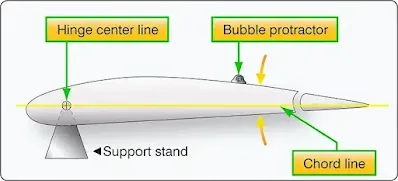
When installing the control surface in the stand or jig, a neutral position should be established with the chord line of the surface in a horizontal position. Use a bubble protractor to determine the neutral position before continuing balancing procedures. [Figure 3]
When installing the control surface in the stand or jig, a neutral position should be established with the chord line of the surface in a horizontal position. Use a bubble protractor to determine the neutral position before continuing balancing procedures. [Figure 3]
 |
| Figure 3. Establishing a neutral position of the control surface |
Sometimes a visual check is all that is needed to determine whether the surface is balanced or unbalanced. Any trim tabs or other assemblies that are to remain on the surface during balancing procedures should be in place. If any assemblies or parts must be removed before balancing, they should be removed.
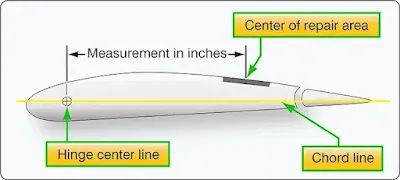
The calculation method of balancing a control surface has one advantage over the other methods in that it can be performed without removing the surface from the aircraft. In using the calculation method, the weight of the material from the repair area and the weight of the materials used to accomplish the repair must be known. Subtract the weight removed from the weight added to get the resulting net gain in the amount added to the surface. The distance from the hinge center line to the center of the repair area is then measured in inches. This distance must be determined to the nearest one-hundredth of an inch. [Figure 4]
Rebalancing Methods
Several methods of balancing (rebalancing) control surfaces are in use by the various manufacturers of aircraft. The most common are the calculation method, scale method, and the balance beam method.The calculation method of balancing a control surface has one advantage over the other methods in that it can be performed without removing the surface from the aircraft. In using the calculation method, the weight of the material from the repair area and the weight of the materials used to accomplish the repair must be known. Subtract the weight removed from the weight added to get the resulting net gain in the amount added to the surface. The distance from the hinge center line to the center of the repair area is then measured in inches. This distance must be determined to the nearest one-hundredth of an inch. [Figure 4]
 |
| Figure 4. Calculation method measurement |
The next step is to multiply the distance times the net weight of the repair. This results in an inch-pounds (in-lb) answer. If the in-lb result of the calculations is within specified tolerances, the control surface is considered balanced. If it is not within specified limits, consult the manufacturer’s service manuals for the needed weights, material to use for weights, design for manufacture, and installation locations for addition of the weights.
The scale method of balancing a control surface requires the use of a scale that is graduated in hundredths of a pound. A support stand and balancing jigs for the surface are also required. Figure 5 illustrates a control surface mounted for rebalancing purposes. Use of the scale method requires the removal of the control surface from the aircraft.
 |
| Figure 5. Balancing setup |
The balance beam method is used by the Cessna and Piper Aircraft companies. This method requires that a specialized tool be locally fabricated. The manufacturer’s maintenance manual provides specific instructions and dimensions to fabricate the tool.
Once the control surface is placed on level supports, the weight required to balance the surface is established by moving the sliding weight on the beam. The maintenance manual indicates where the balance point should be. If the surface is found to be out of tolerance, the manual explains where to place weight to bring it into tolerance.
Aircraft manufacturers use different materials to balance control surfaces, the most common being lead or steel. Larger aircraft manufacturers may use depleted uranium because it has a heavier mass than lead. This allows the counterweights to be made smaller and still retain the same weight. Specific safety precautions must be observed when handling counterweights of depleted uranium because it is radioactive. The manufacturer’s maintenance manual and service instructions must be followed and all precautions observed when handling the weights.
RELATED POSTS
