The purpose of flight controls is to allow the pilot to maneuver the airplane, and to control it from the time it starts the takeoff roll until it lands and safely comes to a halt. Flight controls are typically associated with the wing and the vertical and horizontal stabilizers, because these are the parts of the airplane that flight controls most often attach to. In flight, and to some extent on the ground, flight controls provide the airplane with the ability to move around one or more of the three axes. Flight controls function by changing the shape or aerodynamic characteristics of the surface they are attached to.
The feet of the pilot are on the rudder pedals, and pushing on the left or right rudder pedal makes the rudder move left or right. The trailing edge of the rudder moves to the right, and the nose of the airplane yaws to the right, when the right rudder pedal is pushed. The rudder pedals of a Cessna 182 can be seen in Figure 4.
Even though the rudder of the airplane will make the nose yaw to the left or the right, the rudder is not what turns the airplane. For what is called a coordinated turn to occur, both the ailerons and rudder come into play. Let’s say we want to turn the airplane to the right. We start by turning the control wheel to the right, which raises the right aileron and lowers the left aileron and initiates the banking turn. The increased lift on the left wing also increases the induced drag on the left wing, which tries to make the nose of the airplane yaw to the left. To counteract this, when the control wheel is moved to the right, a small amount of right rudder is used to keep the nose of the airplane from yawing to the left. Once the nose of the airplane is pointing in the right direction, pressure on the rudder is no longer needed. The rudder of a Piper Cherokee Arrow can be seen in Figure 6.
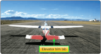
A very common flight control to find fitted with a trim tab is the elevator. In order to be stable in flight, most airplanes have the center of gravity located forward of the center of lift on the wing. This causes a nose heavy condition, which needs to be balanced out by having the elevator deflect upwards and create a downward force. To relieve the pilot of the need to hold back pressure on the control wheel, a trim tab on the elevator can be adjusted to hold the elevator in a slightly deflected position. An elevator trim tab for a Cessna 182 is shown in Figure 7.
The flight controls of a large commercial airliner are shown in Figure 8. The controls by color are as follows:
RELATED POSTS
Flight Controls and the Lateral Axis
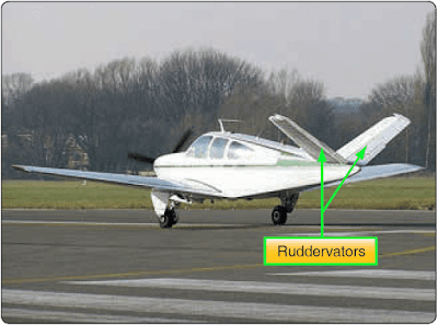
The lateral axis of an airplane is a line that runs below the wing, from wingtip to wingtip, passing through the airplane’s center of gravity. Movement around this axis is called pitch, and control around this axis is called longitudinal control. The flight control that handles this job is the elevator attached to the horizontal stabilizer, a fully moving horizontal stabilizer, or on a v-tail configured airplane, it is called ruddervators. An elevator on a Cessna 182 can be seen in Figure 1. In Figure 2, a fully moving horizontal stabilizer, known as a stabilator, can be seen on a Piper Cherokee Cruiser PA-28-140, and Figure 3 shows a ruddervator on a Beechcraft Bonanza. |
| igure 2. Moving horizontal stabilizer, known as a stabilator, on a Piper Cherokee Cruiser PA-28-140 provides pitch control |
Depending on the airplane being discussed, movement around the lateral axis happens as a result of the pilot moving the control wheel or yoke, the control stick, or on some airplanes, a side stick. On the airplanes shown in Figures 6 and 7, a control wheel or yoke is used.
On the Cessna 182 shown in Figure 1, pulling back on the control wheel causes the trailing edge of the elevator to deflect upward, causing an increased downward force that raises the nose of the airplane. Movement of the elevator causes the nose of the airplane to pitch up or pitch down by rotating around the lateral axis. The Cessna 182 control wheel can be seen in Figure 4.
On the Piper Cherokee Cruiser PA-28-140 shown in Figure 2, pulling back on the control wheel causes the entire horizontal surface, or stabilator, to move, with the trailing edge deflecting upward. The anti-servo tab seen on the Cherokee provides a control feel similar to what would be experienced by moving an elevator. Without this tab, the stabilator might be too easy to move and a pilot could overcontrol the airplane.
The ruddervators shown on the Beechcraft Bonanza in Figure 3 are also moved by the control wheel, with their trailing edges deflecting upward when the control wheel is pulled back. As the name implies, these surfaces also act as the rudder for this airplane.
The ailerons move as a result of the pilot rotating the control wheel to the left or to the right, much the same as turning the steering wheel on an automobile. [Figure 4] When a pilot turns the control wheel to the left, the airplane is being asked to turn or bank to the left. Turning the control wheel to the left causes the trailing edge of the aileron on the left wing to rise up into the airstream, and the aileron on the right wing lowers down into the airstream. This increases the lift on the right wing and decreases the lift on the left wing, causing the right wing to move up and the airplane to bank to the left.
The ruddervators shown on the Beechcraft Bonanza in Figure 3 are also moved by the control wheel, with their trailing edges deflecting upward when the control wheel is pulled back. As the name implies, these surfaces also act as the rudder for this airplane.
Flight Controls and the Longitudinal Axis
The longitudinal axis of the airplane runs through the middle of the airplane, from nose to tail, passing through the center of gravity. Movement around this axis is known as roll, and control around this axis is called lateral control. Movement around this axis is controlled by the ailerons, and on jet transport airplanes, it is aided by surfaces on the wing known as spoilers.The ailerons move as a result of the pilot rotating the control wheel to the left or to the right, much the same as turning the steering wheel on an automobile. [Figure 4] When a pilot turns the control wheel to the left, the airplane is being asked to turn or bank to the left. Turning the control wheel to the left causes the trailing edge of the aileron on the left wing to rise up into the airstream, and the aileron on the right wing lowers down into the airstream. This increases the lift on the right wing and decreases the lift on the left wing, causing the right wing to move up and the airplane to bank to the left.
In Figure 5, an aircraft can be seen doing an aileron roll. Notice that the left aileron is up and the right aileron is down, which would cause the airplane to roll around the longitudinal axis in a counterclockwise direction.
Flight Controls and the Vertical Axis
The vertical axis of an airplane runs from top to bottom through the middle of the airplane, passing through the center of gravity. Movement around this axis is known as yaw, and control around this axis is called directional control. Movement around this axis is controlled by the rudder, or in the case of the Beechcraft Bonanza in Figure 3, by the ruddervators.The feet of the pilot are on the rudder pedals, and pushing on the left or right rudder pedal makes the rudder move left or right. The trailing edge of the rudder moves to the right, and the nose of the airplane yaws to the right, when the right rudder pedal is pushed. The rudder pedals of a Cessna 182 can be seen in Figure 4.
Even though the rudder of the airplane will make the nose yaw to the left or the right, the rudder is not what turns the airplane. For what is called a coordinated turn to occur, both the ailerons and rudder come into play. Let’s say we want to turn the airplane to the right. We start by turning the control wheel to the right, which raises the right aileron and lowers the left aileron and initiates the banking turn. The increased lift on the left wing also increases the induced drag on the left wing, which tries to make the nose of the airplane yaw to the left. To counteract this, when the control wheel is moved to the right, a small amount of right rudder is used to keep the nose of the airplane from yawing to the left. Once the nose of the airplane is pointing in the right direction, pressure on the rudder is no longer needed. The rudder of a Piper Cherokee Arrow can be seen in Figure 6.
Tabs
Trim Tabs
Trim tabs are small movable surfaces that attach to the trailing edge of flight controls. These tabs can be controlled from the flight deck, and their purpose is to create an aerodynamic force that keeps the flight control in a deflected position. Trim tabs can be installed on any of the primary flight controls.A very common flight control to find fitted with a trim tab is the elevator. In order to be stable in flight, most airplanes have the center of gravity located forward of the center of lift on the wing. This causes a nose heavy condition, which needs to be balanced out by having the elevator deflect upwards and create a downward force. To relieve the pilot of the need to hold back pressure on the control wheel, a trim tab on the elevator can be adjusted to hold the elevator in a slightly deflected position. An elevator trim tab for a Cessna 182 is shown in Figure 7.
Anti-servo Tab
Some airplanes, like a Piper Cherokee Arrow, do not have a fixed horizontal stabilizer and movable elevator. The Cherokee uses a moving horizontal surface known as a stabilator. Because of the location of the pivot point for this movable surface, it has a tendency to be extremely sensitive to pilot input. To reduce the sensitivity, a full length anti-servo tab is installed on the trailing edge of the stabilator. As the trailing edge of the stabilator moves down, the anti-servo tab moves down and creates a force trying to raise the trailing edge. With this force acting against the movement of the stabilator, it reduces the sensitivity to pilot input. The anti-servo tab on a Piper Cherokee Arrow is shown in Figure 6.
Balance Tab
On some airplanes, the force needed to move the flight controls can be excessive. In these cases, a balance tab can be used to generate a force that assists in the movement of the flight control. Just the opposite of anti-servo tabs, balance tabs move in the opposite direction of the flight control’s trailing edge, providing a force that helps the flight control move.Servo Tab
On large airplanes, because the force needed to move the flight controls is beyond the capability of the pilot, hydraulic actuators are used to provide the necessary force. In the event of a hydraulic system malfunction or failure, some of these airplanes have servo tabs on the trailing edge of the primary flight controls. When the control wheel is pulled back in an attempt to move the elevator, the servo tab moves and creates enough aerodynamic force to move the elevator. The servo tab is acting like a balance tab, but rather than assisting the normal force that moves the elevator, it becomes the sole force that makes the elevator move. Like the balance tab, the servo tab moves in the opposite direction of the flight control’s trailing edge. The Boeing 727 has servo tabs that back up the hydraulic system in the event of a failure. During normal flight, the servo tabs act like balance tabs. [Figure 8]Supplemental Lift-Modifying Devices
If the wing of an airplane was designed to produce the maximum lift possible at low airspeed, to accommodate takeoffs and landings, it would not be suited for higher speed flight because of the enormous amount of drag it would produce. To give the wing the ability to produce maximum low speed lift without being drag prohibitive, retractable high lift devices, such as flaps and slats, are utilized.Flaps
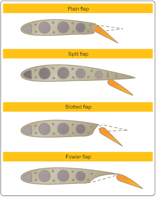
The most often used lift-modifying device, for small airplanes and large, is the wing flap. Flaps can be installed on the leading edge or trailing edge, with the leading edge versions used only on larger airplanes. Flaps change the camber of the wing, and they increase both the lift and the drag for any given angle of attack. The four different types of flaps in use are called the plain, split, slotted, and Fowler. [Figure 9]Plain flaps attach to the trailing edge of the wing, inboard of the ailerons, and form part of the wing’s overall surface. When deployed downward, they increase the effective camber of the wing and the wing’s chord line. Both of these factors cause the wing to create more lift and more drag.
The split flap attaches to the bottom of the wing, and deploys downward without changing the top surface of the wing. This type of flap creates more drag than the plain flap because of the increase in turbulence.
The slotted flap is similar to the plain flap, except when it deploys, the leading edge drops down a small amount. By having the leading edge drop down slightly, a slot opens, which lets some of the high-pressure air on the bottom of the wing flow over the top of the flap. This additional airflow over the top of the flap produces additional lift.
The Fowler flap attaches to the back of the wing using a track and roller system. When it deploys, it moves aft in addition to deflecting downward. This increases the total wing area, in addition to increasing the wing camber and chord line. This type of flap is the most effective of the four types, and it is the type used on commercial airliners and business jets.
Leading Edge Slots
Leading edge slots are ducts or passages in the leading edge of a wing that allow high pressure air from the bottom of the wing to flow to the top of the wing. This ducted air flows over the top of the wing at a high velocity and helps keep the boundary layer air from becoming turbulent and separating from the wing. Slots are often placed on the part of the wing ahead of the ailerons, so during a wing stall, the inboard part of the wing stalls first and the ailerons remain effective.Leading Edge Slats
Leading edge slats serve the same purpose as slots, the difference being that slats are movable and can be retracted when not needed. On some airplanes, leading edge slats have been automatic in operation, deploying in response to the aerodynamic forces that come into play during a high angle of attack. On most of today’s commercial airliners, the leading edge slats deploy when the trailing edge flaps are lowered.The flight controls of a large commercial airliner are shown in Figure 8. The controls by color are as follows:
- All aerodynamic tabs are shown in green.
- All leading and trailing edge high lift devices are shown in red (leading edge flaps and slats, trailing edge inboard and outboard flaps).
- The tail mounted primary flight controls are in orange (rudder and elevator).
- The wing mounted primary flight controls are in purple (inboard and outboard aileron).
RELATED POSTS
- Aircraft Theory of Flight (Part 1)
- Aircraft Stability - Aircraft Theory of Flight (Part 2)
- High Speed Aerodynamics - Aircraft Theory of Flight (Part 4)
- Helicopter Aerodynamics - Aircraft Theory of Flight (Part 5)
- Weight-Shift Control, Flexible Wing Aircraft Aerodynamics - Aircraft Theory of Flight (Part 6)
- Powered Parachute Aerodynamics - Aircraft Theory of Flight (Part 7)
- Simple Machines
- Stress


