One of the differences between a helicopter and a fixed-wing aircraft is the main source of lift. The fixed-wing aircraft derives its lift from a fixed airfoil surface while the helicopter derives lift from a rotating airfoil called the rotor.
During hovering flight in a no-wind condition, the tip-path plane is horizontal, that is, parallel to the ground. Lift and thrust act straight up; weight and drag act straight down. The sum of the lift and thrust forces must equal the sum of the weight and drag forces in order for the helicopter to hover.
During vertical flight in a no-wind condition, the lift and thrust forces both act vertically upward. Weight and drag both act vertically downward. When lift and thrust equal weight and drag, the helicopter hovers; if lift and thrust are less than weight and drag, the helicopter descends vertically; if lift and thrust are greater than weight and drag, the helicopter rises vertically.
For forward flight, the tip-path plane is tilted forward, thus tilting the total lift-thrust force forward from the vertical. This resultant lift-thrust force can be resolved into two components: lift acting vertically upward and thrust acting horizontally in the direction of flight. In addition to lift and thrust, there is weight, the downward acting force, and drag, the rearward acting or retarding force of inertia and wind resistance.
In straight-and-level, unaccelerated forward flight, lift equals weight and thrust equals drag. (Straight-and-level flight is flight with a constant heading and at a constant altitude.) If lift exceeds weight, the helicopter climbs; if lift is less than weight, the helicopter descends. If thrust exceeds drag, the helicopter increases speed; if thrust is less than drag, it decreases speed.
In sideward flight, the tip-path plane is tilted sideward in the direction that flight is desired, thus tilting the total lift-thrust vector sideward. In this case, the vertical or lift component is still straight up, weight straight down, but the horizontal or thrust component now acts sideward with drag acting to the opposite side.
For rearward flight, the tip-path plane is tilted rearward and tilts the lift-thrust vector rearward. The thrust is then rearward and the drag component is forward, opposite that for forward flight. The lift component in rearward flight is straight up; weight, straight down.
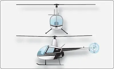
The force that compensates for torque and provides for directional control can be produced by various means. The defining factor is dictated by the design of the helicopter, some of which do not have a torque issue. Single main rotor designs typically have an auxiliary rotor located on the end of the tail boom. This auxiliary rotor, generally referred to as a tail rotor, produces thrust in the direction opposite the torque reaction developed by the main rotor. [Figure 1] Foot pedals in the flight deck permit the pilot to increase or decrease tail rotor thrust, as needed, to neutralize torque effect.
During hovering flight in a no-wind condition, the tip-path plane is horizontal, that is, parallel to the ground. Lift and thrust act straight up; weight and drag act straight down. The sum of the lift and thrust forces must equal the sum of the weight and drag forces in order for the helicopter to hover.
During vertical flight in a no-wind condition, the lift and thrust forces both act vertically upward. Weight and drag both act vertically downward. When lift and thrust equal weight and drag, the helicopter hovers; if lift and thrust are less than weight and drag, the helicopter descends vertically; if lift and thrust are greater than weight and drag, the helicopter rises vertically.
For forward flight, the tip-path plane is tilted forward, thus tilting the total lift-thrust force forward from the vertical. This resultant lift-thrust force can be resolved into two components: lift acting vertically upward and thrust acting horizontally in the direction of flight. In addition to lift and thrust, there is weight, the downward acting force, and drag, the rearward acting or retarding force of inertia and wind resistance.
In straight-and-level, unaccelerated forward flight, lift equals weight and thrust equals drag. (Straight-and-level flight is flight with a constant heading and at a constant altitude.) If lift exceeds weight, the helicopter climbs; if lift is less than weight, the helicopter descends. If thrust exceeds drag, the helicopter increases speed; if thrust is less than drag, it decreases speed.
In sideward flight, the tip-path plane is tilted sideward in the direction that flight is desired, thus tilting the total lift-thrust vector sideward. In this case, the vertical or lift component is still straight up, weight straight down, but the horizontal or thrust component now acts sideward with drag acting to the opposite side.
For rearward flight, the tip-path plane is tilted rearward and tilts the lift-thrust vector rearward. The thrust is then rearward and the drag component is forward, opposite that for forward flight. The lift component in rearward flight is straight up; weight, straight down.
Torque Compensation
Newton’s third law of motion states “To every action there is an equal and opposite reaction.” As the main rotor of a helicopter turns in one direction, the fuselage tends to rotate in the opposite direction. This tendency for the fuselage to rotate is called torque. Since torque effect on the fuselage is a direct result of engine power supplied to the main rotor, any change in engine power brings about a corresponding change in torque effect. The greater the engine power, the greater the torque effect. Since there is no engine power being supplied to the main rotor during autorotation, there is no torque reaction during autorotation.The force that compensates for torque and provides for directional control can be produced by various means. The defining factor is dictated by the design of the helicopter, some of which do not have a torque issue. Single main rotor designs typically have an auxiliary rotor located on the end of the tail boom. This auxiliary rotor, generally referred to as a tail rotor, produces thrust in the direction opposite the torque reaction developed by the main rotor. [Figure 1] Foot pedals in the flight deck permit the pilot to increase or decrease tail rotor thrust, as needed, to neutralize torque effect.
 |
| Figure 1. Single rotor helicopter |
Other methods of compensating for torque and providing directional control include the Fenestron® tail rotor system, an SUD Aviation design that employs a ducted fan enclosed by a shroud. Another design, called NOTAR®, a McDonald Douglas design with no tail rotor, employs air directed through a series of slots in the tail boom, with the balance exiting through a 90° duct located at the rear of the tail boom. [Figure 2]
 |
| Figure 2. Aerospatiale Fenestron tail rotor system (left) and the McDonnell Douglas NOTAR® System (right) |
Gyroscopic Forces
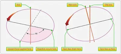
The spinning main rotor of a helicopter acts like a gyroscope. As such, it has the properties of gyroscopic action, one of which is precession. Gyroscopic precession is the resultant action or deflection of a spinning object when a force is applied to this object. This action occurs approximately 90° in the direction of rotation from the point where the force is applied. [Figure 3] Through the use of this principle, the tip-path plane of the main rotor may be tilted from the horizontal. |
| Figure 3. Gyroscopic precession principle |
Examine a two-bladed rotor system to see how gyroscopic precession affects the movement of the tip-path plane. Moving the cyclic pitch control increases the angle of attack (AOA) of one rotor blade with the result that a greater lifting force is applied at that point in the plane of rotation. This same control movement simultaneously decreases the AOA of the other blade the same amount, thus decreasing the lifting force applied at that point in the plane of rotation.
The blade with the increased AOA tends to flap up; the blade with the decreased AOA tends to flap down. Because the rotor disk acts like a gyro, the blades reach maximum deflection at a point approximately 90° later in the plane of rotation. As shown in Figure 4, the retreating blade AOA is increased and the advancing blade AOA is decreased resulting in a tipping forward of the tip-path plane, since maximum deflection takes place 90° later when the blades are at the rear and front, respectively. In a rotor system using three or more blades, the movement of the cyclic pitch control changes the AOA of each blade an appropriate amount so that the end result is the same.
 |
| Figure 4. Gyroscopic precession |
The movement of the cyclic pitch control in a two-bladed rotor system increases the AOA of one rotor blade with the result that a greater lifting force is applied at this point in the plane of rotation. This same control movement simultaneously decreases the AOA of the other blade a like amount, thus decreasing the lifting force applied at this point in the plane of rotation. The blade with the increased AOA tends to rise; the blade with the decreased AOA tends to lower. However, gyroscopic precession prevents the blades from rising or lowering to maximum deflection until a point approximately 90° later in the plane of rotation.
In a three-bladed rotor, the movement of the cyclic pitch control changes the AOA of each blade an appropriate amount so that the end result is the same, a tipping forward of the tip-path plane when the maximum change in AOA is made as each blade passes the same points at which the maximum increase and decrease are made for the twobladed rotor as shown in Figure 4. As each blade passes the 90° position on the left, the maximum increase in AOA occurs. As each blade passes the 90° position to the right, the maximum decrease in AOA occurs. Maximum deflection takes place 90° later, maximum upward deflection at the rear and maximum downward deflection at the front; the tip-path plane tips forward.
RELATED POSTS
