DC Motor Construction
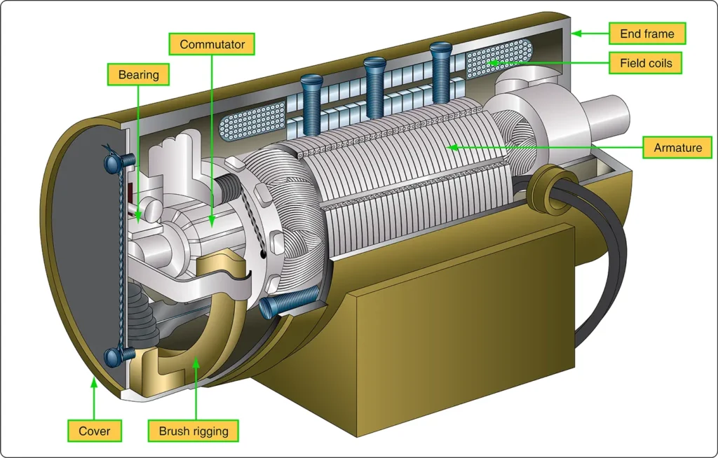
The major parts of a practical DC motor are the armature assembly, the field assembly, the brush assembly, and the end frame. [Figure 1]
Armature Assembly
The armature assembly contains a laminated soft-iron core, coils, and a commutator, all mounted on a rotatable steel shaft. The armature core is formed from a stack of soft-iron laminations insulated from one another. Solid iron is not used because a solid iron core rotating in a magnetic field would develop excessive eddy currents, resulting in unnecessary heating and energy loss.
The armature windings consist of insulated copper wire inserted into slots lined with insulating material, such as fiber paper (fish paper), to protect the windings. The ends of the windings are connected to the commutator segments. Wedges or steel bands hold the windings in place to prevent them from being thrown out of the slots when the armature rotates at high speeds.
The commutator consists of a large number of copper segments insulated from one another and from the armature shaft by pieces of mica. Insulated wedge rings hold the segments in place.
Field Assembly
The field assembly consists of the field frame, the pole pieces, and the field coils. The field frame is located along the inner wall of the motor housing. It supports laminated soft-steel pole pieces around which the field coils are wound.
A coil, consisting of several turns of insulated wire, fits over each pole piece. The coil and pole piece together constitute a field pole. Some motors have as few as two poles, while others have as many as eight.
Brush Assembly
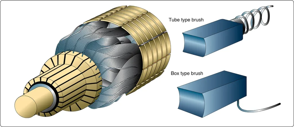
The brush assembly consists of the brushes and their holders. The brushes are usually small blocks of graphitic carbon because this material has a long service life and causes minimum wear to the commutator.
The holders permit some movement of the brushes so that they can follow irregularities in the commutator surface and maintain good electrical contact. Springs hold the brushes firmly against the commutator. [Figure 2]
End Frame
The end frame is the part of the motor opposite the commutator. Usually, the end frame is designed so that it can be connected to the unit to be driven. The bearing for the drive end is also located in the end frame.
Sometimes, the end frame is made part of the unit driven by the motor. In such cases, the drive-end bearing may be located in the driven unit.
Types of DC Motors
There are three basic types of DC motors: series motors, shunt motors, and compound motors. They differ primarily in the manner in which their field and armature windings are connected.
Series DC Motor
In a series motor, the field winding, consisting of a relatively few turns of heavy wire, is connected in series with the armature winding. Both diagrammatic and schematic illustrations of a series motor are shown in Figure 3.
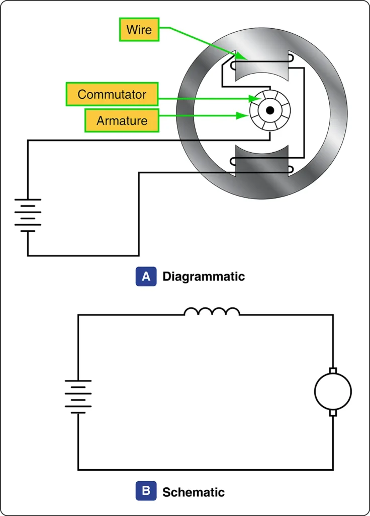
The same current flows through both the field winding and the armature winding. Therefore, an increase in current strengthens the magnetic fields produced by both the field and armature windings.
Because of the low resistance of the windings, the series motor draws a large current during starting. This starting current, flowing through both the field and armature windings, produces a high starting torque, which is the principal advantage of the series motor.
The speed of a series motor is highly dependent on the load. Any change in load is accompanied by a substantial change in speed. A series motor runs at high speed under a light load and at low speed under a heavy load. If the load is removed entirely, the motor may accelerate to an excessively high speed, potentially causing the armature to disintegrate.
Series motors are used in applications requiring high starting torque under heavy-load conditions. In aircraft, they are often used as engine starters and for raising and lowering landing gear, cowl flaps, and wing flaps.
Shunt DC Motor
In a shunt motor, the field winding is connected in parallel, or in shunt, with the armature winding. [Figure 4] The field winding has a high resistance. Since it is connected across the power supply, the field current remains approximately constant when the supply voltage is constant.
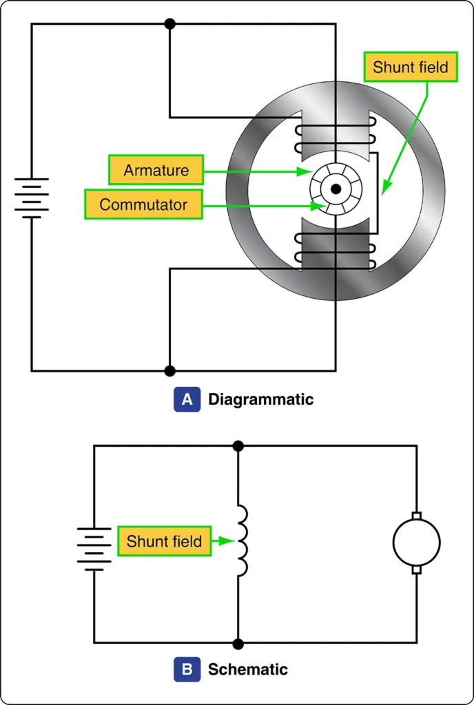
Unlike the field current in a series motor, the shunt field current is largely independent of changes in motor load and speed. Consequently, the torque of a shunt motor varies primarily with the current flowing through the armature, assuming the field flux remains approximately constant.
The starting torque of a shunt motor is lower than that of a series motor of equal size.
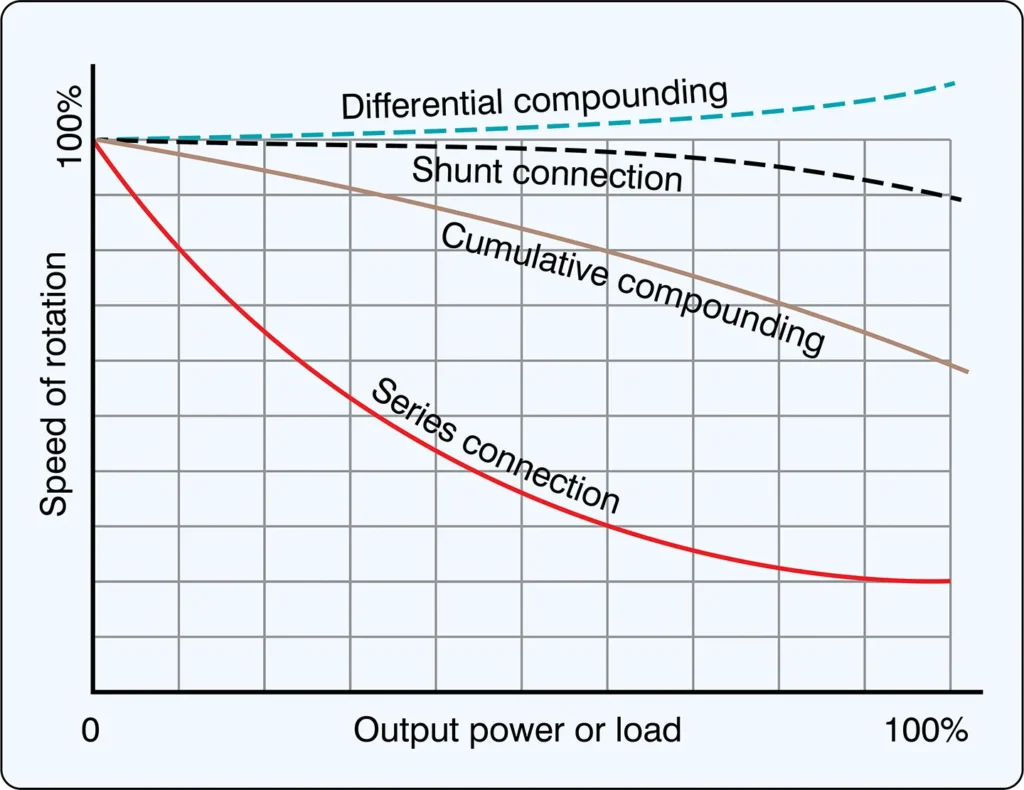
The speed of a shunt motor varies very little with changes in load. When the load is removed, the motor assumes a speed slightly higher than its loaded speed. This motor is particularly suitable for applications requiring nearly constant speed when high starting torque is not necessary.
Compound DC Motor
The compound motor is a combination of the series and shunt motors. It has two field windings: a shunt winding and a series winding. [Figure 5]
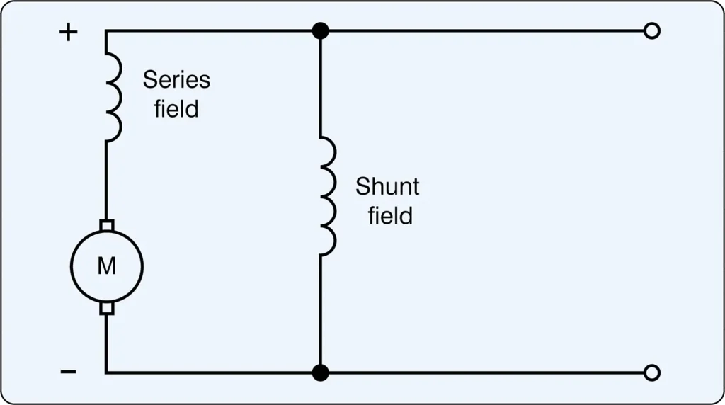
The shunt winding consists of many turns of fine wire and is connected in parallel with the armature winding. The series winding consists of a few turns of heavy wire and is connected in series with the armature winding.
The starting torque of a compound motor is generally higher than that of a shunt motor but lower than that of a series motor. Its speed variation with load is less than that of a series motor but greater than that of a shunt motor. The compound motor is used whenever the combined characteristics of series and shunt motors are desired.
Like the compound generator, the compound motor has both series and shunt field windings. The series winding may either aid the shunt winding (cumulative compound) or oppose the shunt winding (differential compound).
The starting and load characteristics of a cumulative compound motor lie between those of series and shunt motors.
Because of its series field, the cumulative compound motor has a higher starting torque than a shunt motor. Cumulative compound motors are used to drive machines subject to sudden changes in load. They are also used where high starting torque is desired but a series motor cannot be used conveniently.
In a differential compound motor, an increase in load causes an increase in armature current. This strengthens the series field, which opposes the shunt field, reducing the total magnetic flux. The reduction in flux tends to increase the motor speed as the load increases. This characteristic can make the motor unstable, and differential compound motors are rarely used in aircraft systems.
A graph showing the variation in speed with changes in load for the various types of DC motors is shown in Figure 6.