
Many certified engines are used with light-sport and experimental aircraft. Generally, cost is a big factor when considering this type of powerplant. The certified engines tend to be much more costly than the non-certified engines, and are not ASTM approved.
Rotax 912/914
Figure 1 shows a typical four cylinder, four-stroke Rotax horizontally opposed engine. The opposed-type engine has two banks of cylinders directly opposite each other with a crankshaft in the center. The pistons of both cylinder banks are connected to the single crankshaft. The engine cylinder heads are both liquid cooled and air cooled; the aircooling is mostly used on the cylinder. It is generally mounted with the cylinders in a horizontal position.
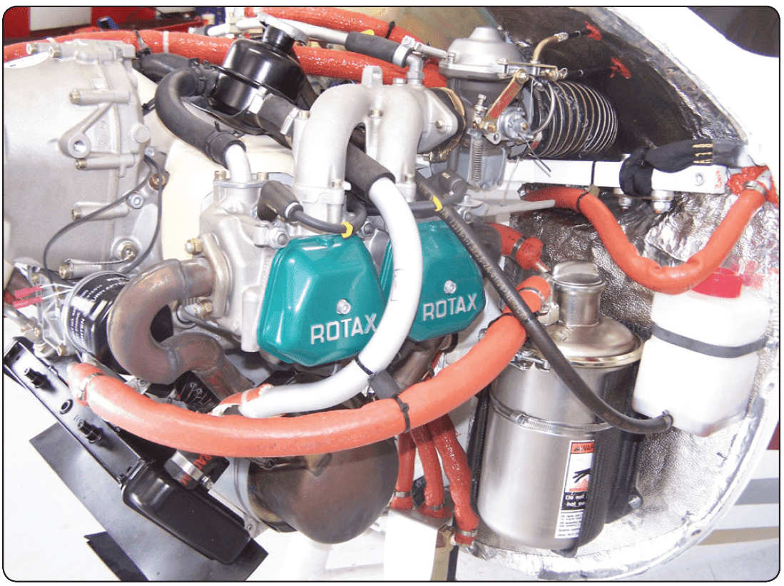 |
| Figure 1. Typical four cylinder, four-stroke horizontally opposed engine |
Description of Systems
Cooling System
The cooling system of the Rotax 914, shown in Figure 2, is designed for liquid cooling of the cylinder heads and ram-air cooling of the cylinders. The cooling system of the cylinder heads is a closed circuit with an expansion tank. [Figure 3] The coolant flow is forced by a water pump driven from the camshaft, from the radiator, to the cylinder heads. From the top of the cylinder heads, the coolant passes on to the expansion tank (1). Since the standard location of the radiator (2) is below engine level, the expansion tank located on top of the engine allows for coolant expansion.
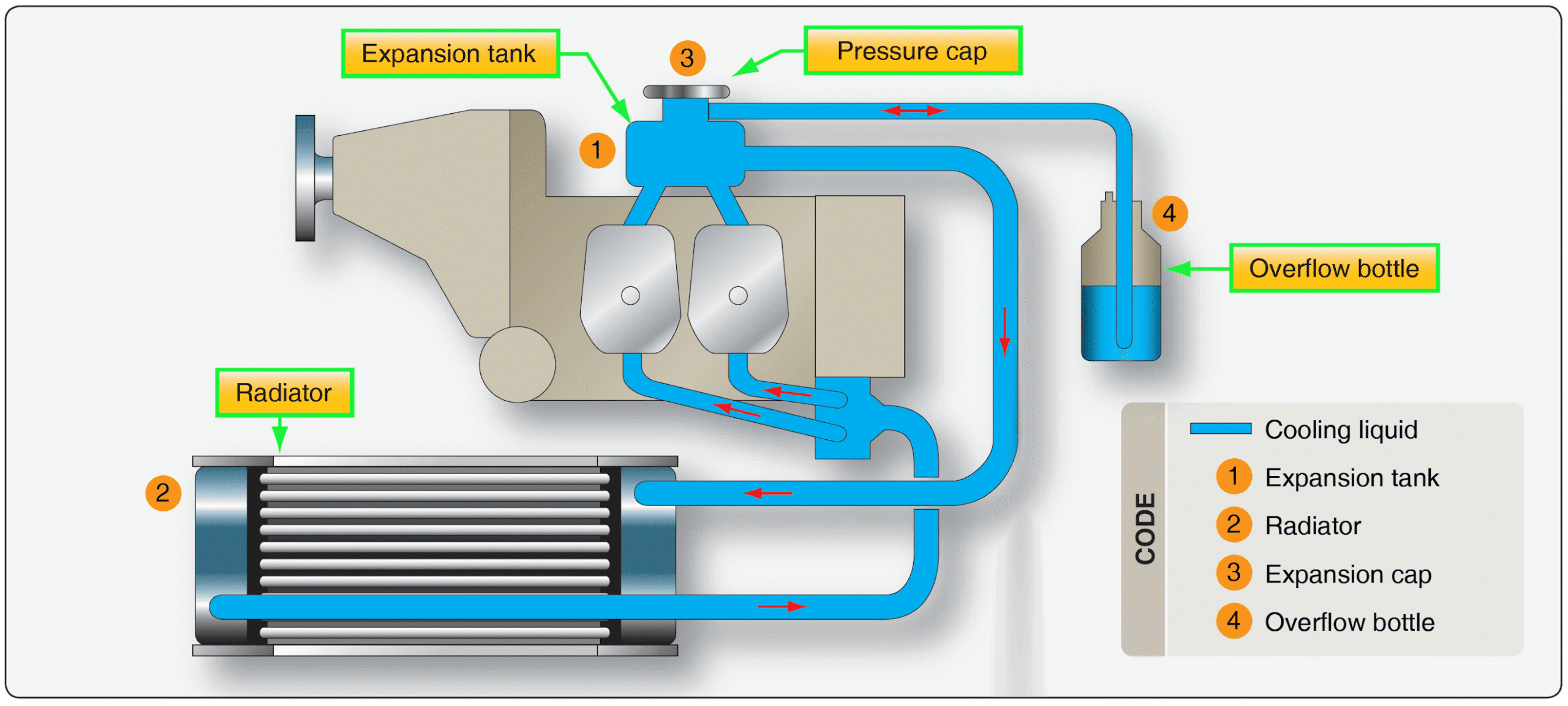 |
| Figure 2. Rotax 914 cooling system |
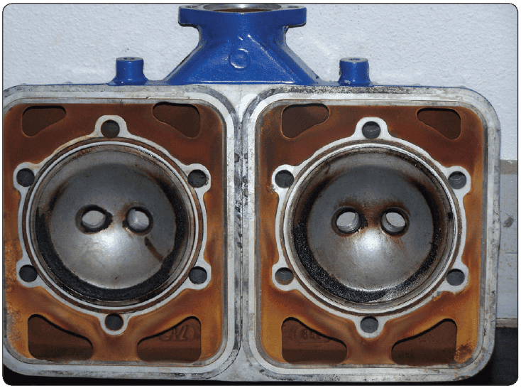 |
| Figure 3. Water-cooled heads |
Fuel System
The fuel flows from the tank (1) via a coarse filter/water trap (2) to the two electric fuel pumps (3) connected in series. [Figure 4] From the pumps, fuel passes on via the fuel pressure control (4) to the two carburetors (5). Parallel to each fuel pump is a separate check valve (6) installed via the return line (7) that allows surplus fuel to flow back to the fuel tank. Inspection for possible constriction of diameter or obstruction must be accomplished to avoid overflowing of fuel from the carburetors. The return line must not have any resistance to flow. The fuel pressure control ensures that the fuel pressure is always maintained approximately 0.25 bar (3.63 pounds per square inch (psi)) above the variable boost pressure in the airbox and thus, ensures proper operation of the carburetors.
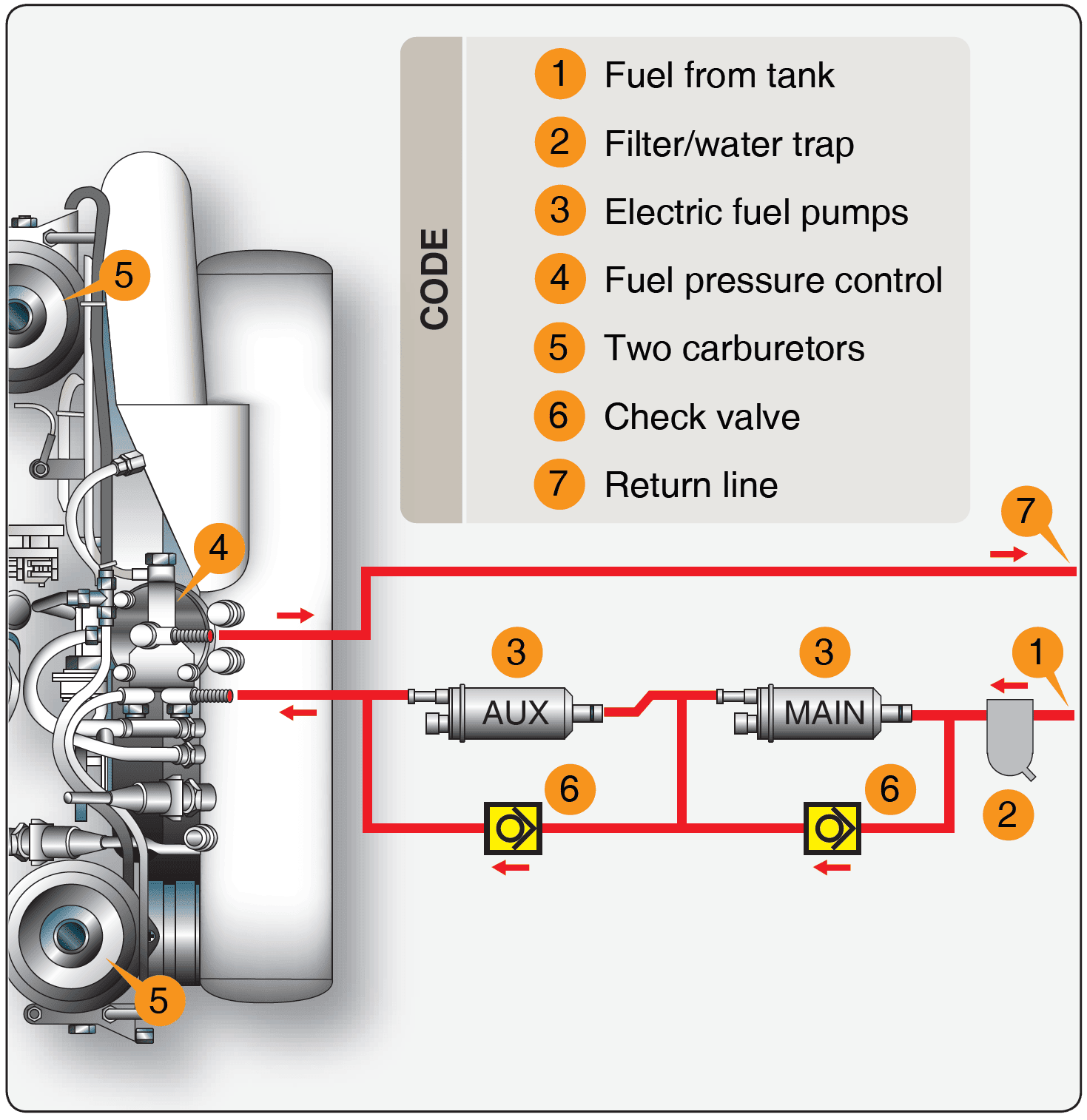 |
| Figure 4. Fuel system components |
Lubrication System
The Rotax 914 engine is provided with a dry, sump-forced lubrication system with a main oil pump with integrated pressure regulator and an additional suction pump. [Figure 5] The oil pumps are driven by the camshaft. The main oil pump draws oil from the oil tank (1) via the oil cooler (2) and forces it through the oil filter to the points of lubrication. It also lubricates the plain bearings of the turbocharger and the propeller governor. The surplus oil emerging from the points of lubrication accumulates on the bottom of crankcase and is forced back to the oil tank by the blow-by gases. The turbocharger is lubricated via a separate oil line (from the main oil pump). The oil emerging from the lower placed turbocharger collects in the oil sump by a separate pump and is pumped back to the oil tank via the oil line (3). The oil circuit is vented via bore (5) in the oil tank.
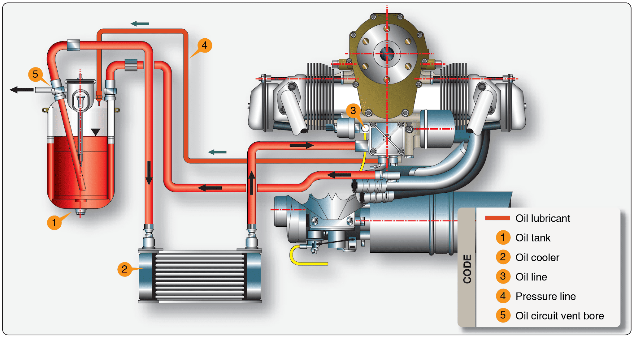 |
| Figure 5. Lubrication system |
Electric System
The Rotax 914 engine is equipped with a dual ignition unit that uses a breakerless, capacitor discharge design with an integrated generator. [Figure 6] The ignition unit is completely free of maintenance and needs no external power supply. Two independent charging coils (1) located on the generator stator supply one ignition circuit each. The energy is stored in capacitors of the electronic modules (2). At the moment of ignition, two each of the four external trigger coils (3) actuate the discharge of the capacitors via the primary circuit of the dual ignition coils (4). The firing order is as follows: 1-4-2-3. The fifth trigger coil (5) is used to provide the revolution counter signal.
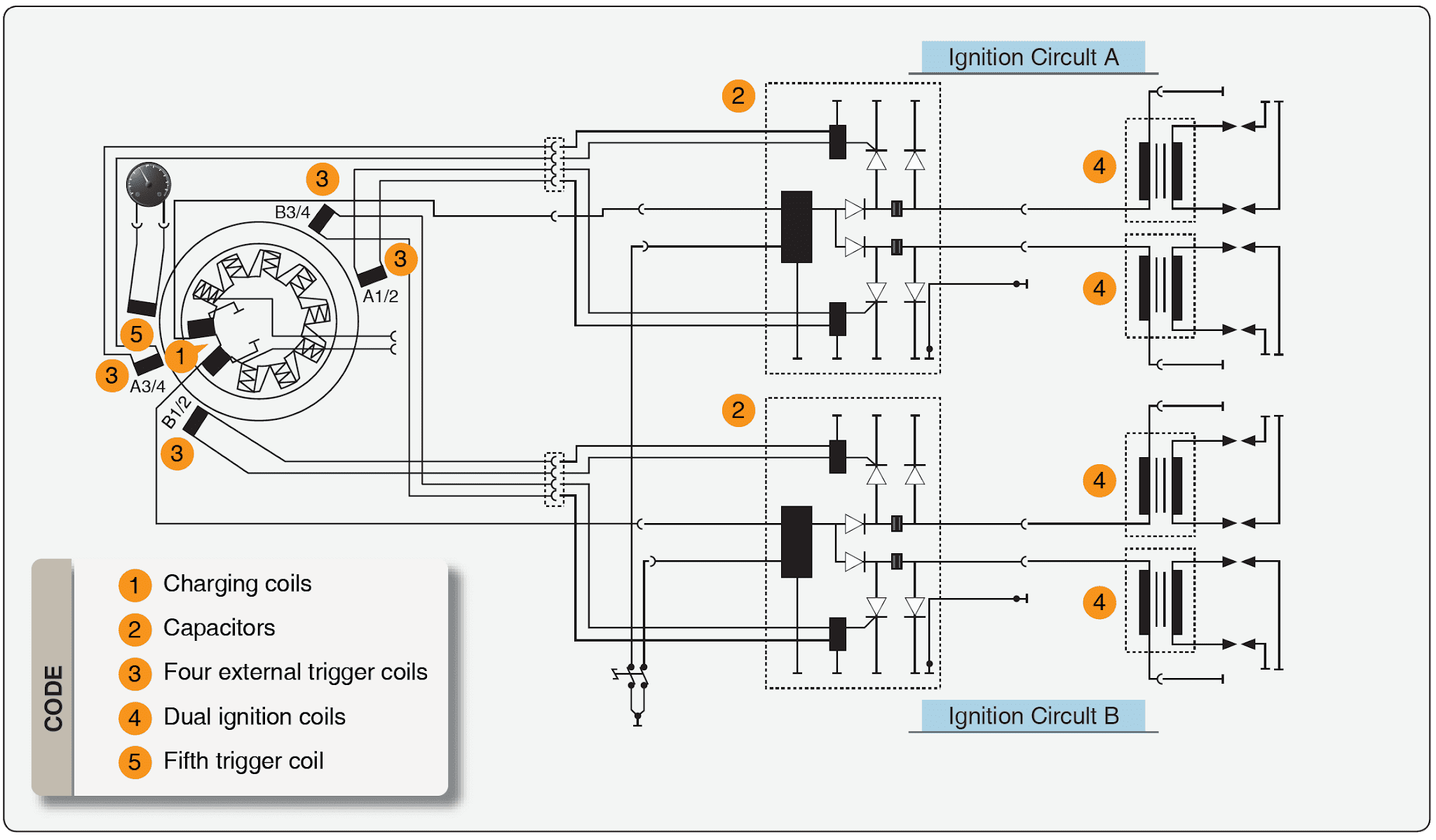 |
| Figure 6. Electric system |
Turbocharger and Control System
The Rotax 914 engine is equipped with an exhaust gas turbocharger making use of the energy in the exhaust gas for compression of the intake air or for providing boost pressure to the induction system. The boost pressure in the induction system (airbox) is controlled by means of an electronically controlled valve (wastegate) in the exhaust gas turbine. The wastegate regulates the speed of the turbocharger and consequently the boost pressure in the induction system. The required nominal boost pressure in the induction system is determined by the throttle position sensor mounted on the carburetor 2/4. The sensor’s transmitted position is linear from 0 to 115 percent, corresponding to a throttle position from idle to full power. [Figure 7] For correlation between throttle position and nominal boost pressure in the induction, refer to Figure 8. As shown in the diagram, with the throttle position at 108–110 percent results in a rapid rise of nominal boost pressure.
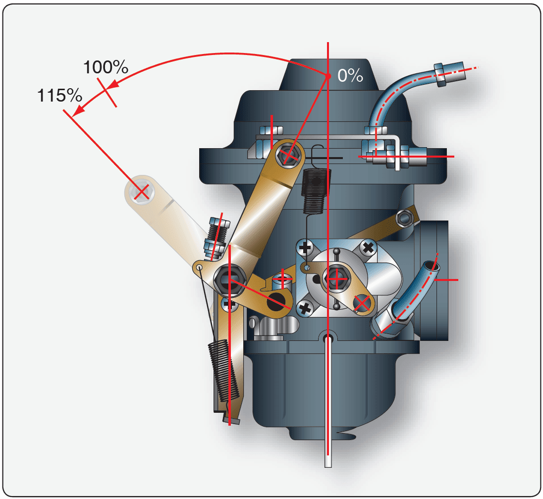 |
| Figure 7. Turbocharger control system throttle range and position |
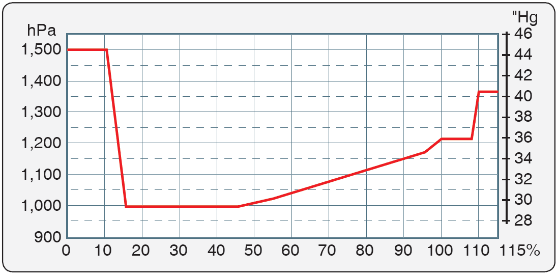 |
| Figure 8. Correlation between throttle position and nominal boost pressure |
The turbo control unit (TCU) is furnished with output connections for an external red boost lamp and an orange caution lamp for indications of the functioning of the TCU. When switching on the voltage supply, the two lamps are automatically subject to a function test. Both lamps illuminate for one to two seconds, then they extinguish. If they do not, a check per the engine maintenance manual is necessary. If the orange caution lamp is not illuminated, then this signals that TCU is ready for operation. If the lamp is blinking, this indicates a malfunction of the TCU or its periphery systems. Exceeding of the admissible boost pressure activates and illuminates the red boost lamp continuously. The TCU registers the time of full throttle operation (boost pressure). Full throttle operation for longer than 5 minutes, with the red boost light illuminated, makes the red boost lamp start blinking. The red boost lamp helps the pilot to avoid full power operation for longer than 5 minutes or the engine could be subject to thermal and mechanical overstress.
HKS 700T Engine
The HKS 700T engine is a four-stroke, two cylinder turbocharged engine equipped with an intercooler. [Figure 9] The horizontally opposed cylinders house four valves per cylinder, with a piston displacement of 709 cc. It uses an electronic control fuel injection system. A reduction gearbox is used to drive the propeller flange at a speed reduction ratio of 2.13 to 1. The engine is rated at 77 horsepower continuous and 80 horsepower takeoff (3 minutes) at 4,900 rpm and 5,300 rpm, respectively. A total engine weight of 126 pounds provides a good power to weight ratio. The 700T has a TBO of 500 hours.
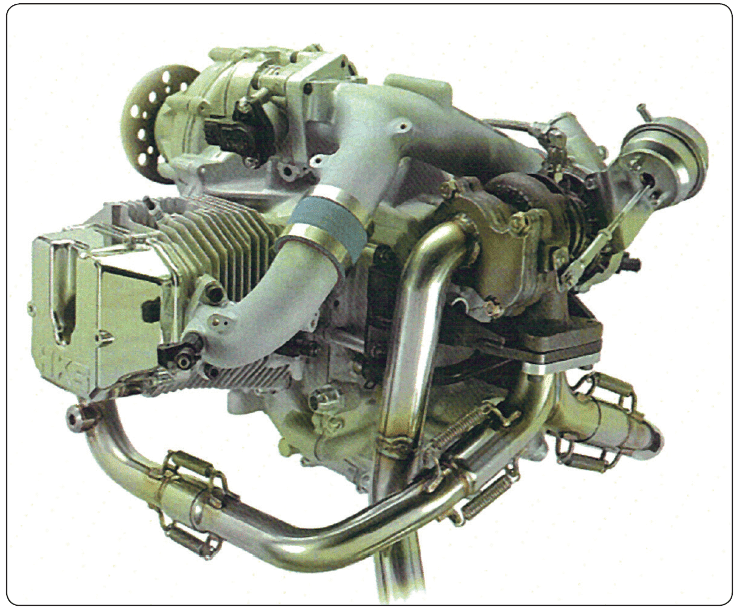 |
| Figure 9. HKS 700T engine |
Jabiru Light-Sport Engines
Jabiru engines are designed to be manufactured using the latest manufacturing techniques. [Figure 10] All Jabiru engines are manufactured, assembled, and ran on a Dynometer, then calibrated before delivery. The crankcase halves, cylinder heads, crankshaft, starter motor housings, gearbox cover (the gearbox powers the distributor rotors), together with many smaller components are machined from solid material. The sump (oil pan) is the only casting. The cylinders are machined from bar 4140 chrome molybdenum alloy steel, with the pistons running directly in the steel bores. The crankshaft is also machined from 4140 chrome molybdenum alloy steel, the journals of which are precision ground prior to being Magnaflux inspected. The camshaft is manufactured from 4140 chrome molybdenum alloy steel with nitrided journals and cams.
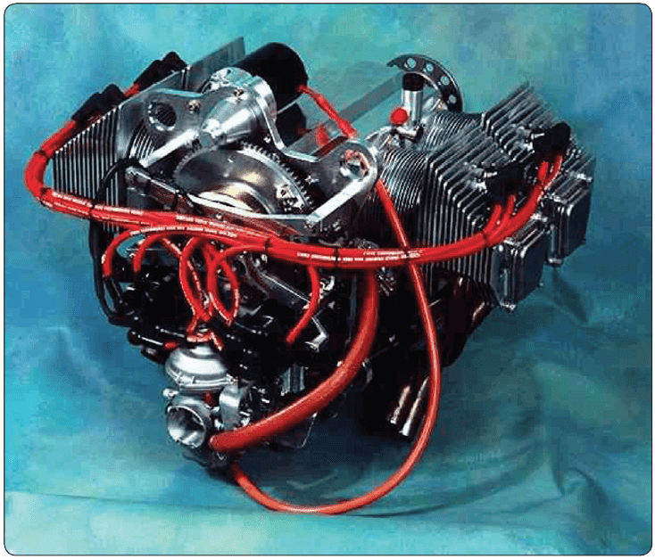 |
| Figure 10. Jabiru engines |
An integral alternator provides AC rectification for battery charging and electrical accessories. The alternator is attached to the flywheel and is driven directly by the crankshaft. The ignition system is a transistorized electronic system; two fixed coils mounted adjacent to the flywheel are energized by magnets attached to the flywheel. The passing of the coils by the magnets creates the high voltage current, that is transmitted by high tension leads to the center post of two automotive type distributors, which are simply rotors and caps, before distribution to automotive spark plugs (two in the top of each cylinder head). The ignition system is fixed timing and, therefore, removes the need for timing adjustment. It is suppressed to prevent radio interference.
The ignition system is fully redundant, self-generating, and does not depend on battery power. The crankshaft is designed with a double bearing at the propeller flange end and a main bearing between each big end. Thrust bearings are located fore and aft of the front double bearing, allowing either tractor or pusher installation. Pistons are remachined to include a piston pin, circlip, and groove. They are all fitted with three rings, the top rings being cast iron to complement the chrome molybdenum cylinder bores. Valves are 7mm (stem diameter) and are manufactured specifically for the Jabiru engine. The valve drive train includes pushrods from the camshaft from the camshaft followers to valve rockers. The valves are Computer Numerical Control (CNC) machined from steel billet, induction hardened, polished on contact surfaces, and mounted on a shaft through Teflon coated bronze-steel bush. Valve guides are manufactured from aluminum/bronze. Replaceable valve seats are of nickel steel and are shrunk into the aluminum cylinder heads. The valve train is lubricated from the oil gallery. Engines use hydraulic lifters that automatically adjust valve clearance. An internal gear pump is driven directly by the camshaft and provides engine lubrication via an oil circuit that includes an automotive spin-on filter, oil cooler and built-in relief valve.
The engine is fitted with a 1.5 kilowatt starter motor that is also manufactured by Jabiru and provides very effective starting. The engine has very low vibration level; however, it is also supported by four large rubber shock mounts attached to the engine mounts at the rear of the engine. The fuel induction system uses a pressure compensating carburetor. Following the carburetor, the fuel/air mixture is drawn through a swept plenum chamber bolted to the sump casting, in which the mixture is warmed prior to entering short induction tubes attached to the cylinder heads.
An effective stainless steel exhaust and muffler system is fitted as standard equipment ensuring very quiet operations. For owners wanting to fit vacuum instruments to their aircraft, the Jabiru engines are designed with a vacuum pump drive direct mounted through a coupling on the rear of the crankshaft.
Jabiru 2200 Aircraft Engine
The Jabiru 2200cc aircraft engine is a four-cylinder, four-stroke horizontally opposed air cooled engine. At 132 pounds (60kgs) installed weight, it is one of the lightest four-cylinder, four-stroke aircraft engines. Small overall dimensions give it a small frontal area width (23.46 in, 596mm) that makes it a good engine for tractor applications. The Jabiru engine is designed for either tractor or pusher installation. The Jabiru engine specifications are listed in Figure 11.
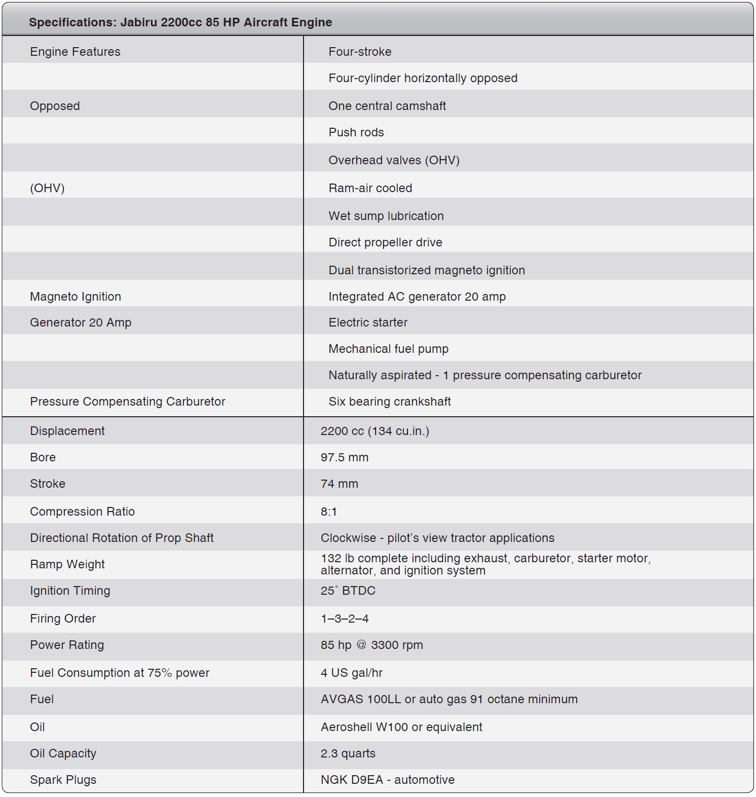 |
| Figure 11. Jabiru 2200cc specifications |
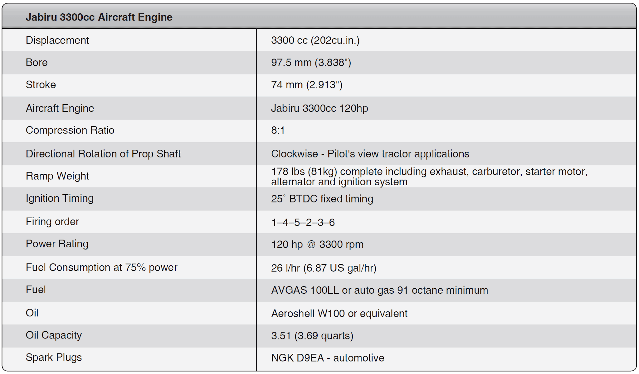 |
| Figure 12. Jabiru 3300cc aircraft engine |
- 4-stroke
- 3300cc engine (200 cubic inches)
- 6-cylinder horizontally opposed
- 1 central camshaft
- Fully machined aluminum alloy crankcase
- Overhead valves (OHV) – push rod operated
- Ram-air cooled
- Wet sump lubrication – 4 liter capacity
- Direct propeller drive
- Dual transistorized magneto ignition
- Integrated AC generator
- Electric starter
- Mechanical fuel pump
- Naturally aspirated – 1 pressure compensation carburetor
Aeromax Aviation 100 (IFB) Aircraft Engine
Aeromax Aviation produces a version of a 100 hp engine called the Integral Front Bearing. The engine features a special made integral front bearing. [Figure 13] The engine uses an integral permanent magnet 35 amp alternator, lightweight starter, and dual ignition. The compact alternator and starter allow for a streamlined and aerodynamic cowl which improves the fuel efficiency of an experimental aircraft. The Aeromax aircraft engine is an opposed six-cylinder, air-cooled, and direct drive. Being a six-cylinder engine, it has smooth operation. The Aeromax engines are known for their heat dissipation qualities, provided the proper amount of cooling air is provided.
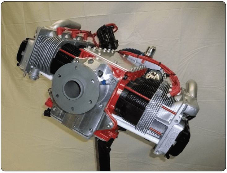 |
| Figure 13. Aeromax direct drive, air-cooled, six-cylinder engine |
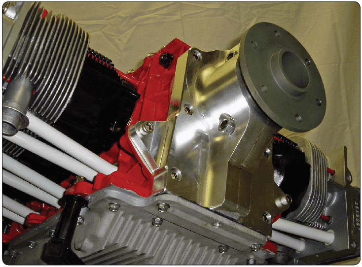 |
| Figure 14. Front-end bearing on the 1000 IFB engine |
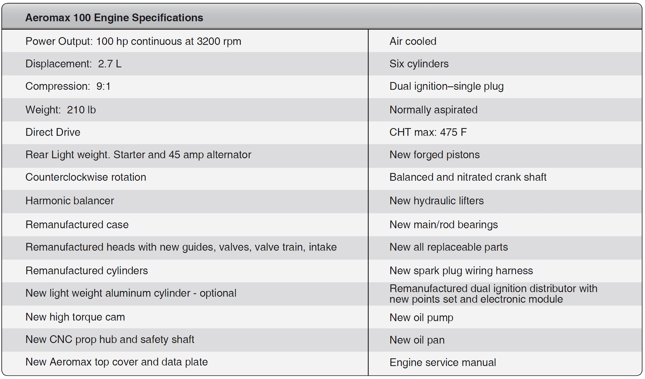 |
| Figure 15. Aeromax 100 engine specifications |
- Engine General Requirements
- Personnel Authorized to Perform Inspection and Maintenance on Light-sport Engines
- Types of Light-Sport and Experimental Engines
- Direct Drive VW Engines
- Maintenance Schedule Procedures and Maintenance Checklist
- Lubrication System Maintenance
- Preflight Checks, Troubleshooting, Abnormal Operation and Preservation
- Light-Sport Jabiru Engines Maintenance Practices and Engine Inspection Charts