
Aircraft drawings provide essential information for the design, manufacture, maintenance, and repair of aircraft and their components. They communicate details such as component dimensions, materials, construction, assembly, and installation. Understanding the different types of aircraft drawings, their purposes, and proper handling practices helps aviation maintenance technicians interpret technical information and perform maintenance tasks accurately.
Computer Graphics
From the early days of aviation, the development of aircraft, aircraft engines, and other components relied heavily on aircraft drawings. For most of the 20th century, drawings were created on a drawing board using pens or pencils and paper. With the introduction and advancement of computers during the later decades of the 20th century, the way drawings were created changed dramatically.
Computers were used not only to create drawings but also to display objects in virtual environments from different viewing angles. Further development of computer software made it possible to assemble separately designed parts virtually to check for proper fit and identify possible interferences. Computer networking and the Internet also made it easier for designers and manufacturers to share their work across different locations.
Computer-controlled manufacturing techniques made it possible to design a part and manufacture it precisely using digital design data, without necessarily producing a paper drawing. Several terms and acronyms became commonly used in computer-aided design and manufacturing.
The more common terms are:
- Computer Graphics: Drawing or creating visual representations using a computer.
- Computer-Aided Design (CAD): The use of computers to design a part, component, or product.
- Computer-Aided Design and Drafting (CADD): The use of computers in both the design and drafting processes.
- Computer-Aided Manufacturing (CAM): The use of computers to plan, control, or support the manufacturing of a part or product.
- Computer-Aided Engineering (CAE): The use of computer-based tools to support engineering activities, such as analysis, simulation, and evaluation of a part or product.
As computer hardware and software continue to evolve, engineering activities can often be completed more efficiently and at lower cost. In addition to product design, CAE applications include product analysis, assembly evaluation, simulations, and the development of maintenance information. [Figure 1]
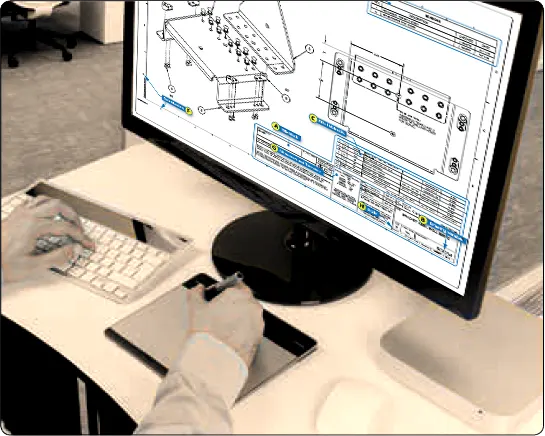
CATIA, Pro/ENGINEER, SolidWorks, and Unigraphics are examples of CAD software packages used in aircraft design and manufacturing. Aircraft manufacturers use computer-based design systems to develop and assemble aircraft digitally before production. Drawings of individual aircraft parts can be created and accessed through these systems.
Computer-based models allow components to be viewed from different angles rather than being limited to the traditional two-dimensional views shown on paper drawings. Technicians may also access drawings and aircraft maintenance manuals using computers, laptops, or mobile devices when performing maintenance tasks.
Purpose and Function of Aircraft Drawings
Drawings and prints provide the link between the engineers who design an aircraft and the workers who build, maintain, and repair it. A print may be a copy of a working drawing for an aircraft part or group of parts, or for the design of a system or group of systems.
Traditionally, aircraft drawings were reproduced using photographic processes such as blueprinting. In a traditional blueprint process, a tracing of the drawing was placed over chemically treated paper and exposed to light. The areas exposed to light produced a blue background, while the lines blocked by the tracing appeared white. Other reproduction methods produced prints with different background and line colors.
Today, aircraft drawings are commonly accessed and distributed electronically. They may also be printed as hard copies using printers or plotters when required.
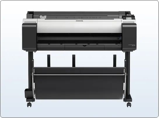
Drawings created using computers may be viewed on a computer monitor or printed using an inkjet or laser printer. Larger drawings may be produced using plotters or large-format printers. These devices can produce drawings at the required scale for design, manufacturing, inspection, and maintenance purposes. [Figure 2]
Care and Use of Drawings
Aircraft drawings should be handled carefully because they are valuable technical documents. When opening a folded drawing, unfold it slowly and carefully to prevent tearing. Once the drawing is open, smooth out the existing fold lines rather than bending them backward.
To protect drawings from damage, never spread them on the floor or place them on surfaces covered with tools or other objects that could puncture or damage the paper. Hands should be free of oil, grease, and other contaminants that may soil or smudge the drawing.
Drawings should not be marked or altered in a way that could confuse others or lead to incorrect work. Any required notes or changes must be made by authorized personnel in accordance with the applicable drawing-control procedures. Changes should be properly identified, signed, and dated when required by those procedures.
When finished using a drawing, fold it and return it to its proper storage location. Drawings are generally folded to a suitable size for filing. Care should be taken to use the original fold lines to avoid unnecessary damage.
Types of Drawings
Aircraft drawings must provide information such as the size and shape of an object and its parts, the materials to be used, the required finish, how the parts are assembled, and any other information essential to manufacturing and assembly.
Aircraft drawings may be divided into three main classes: detail drawings, assembly drawings, and installation drawings.
Detail Drawing
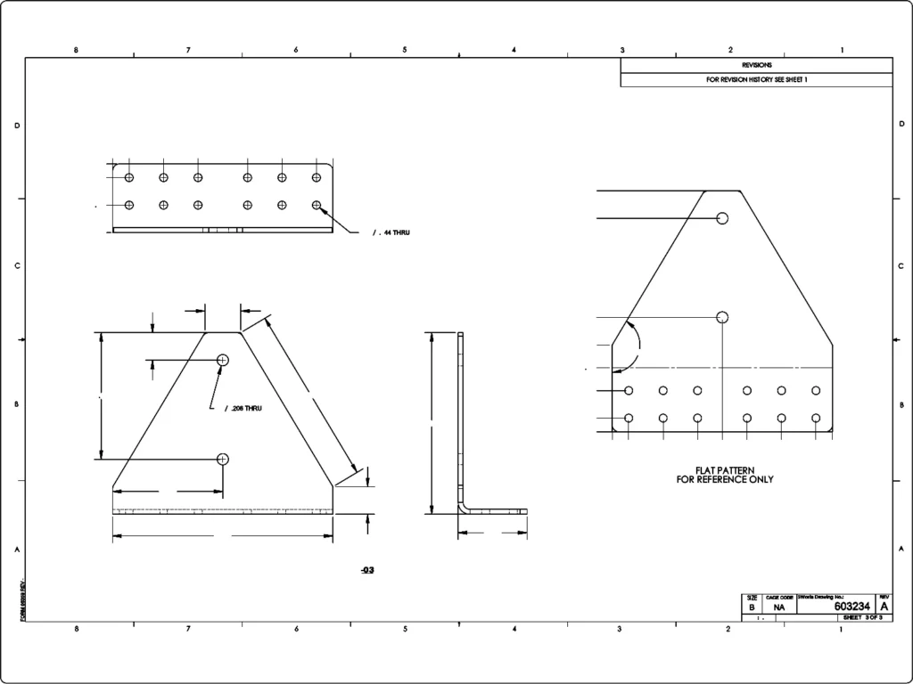
A detail drawing describes a single part using lines, notes, and symbols to specify its size, shape, material, and manufacturing requirements. Detail drawings are usually relatively simple. When individual parts are small, several detail drawings may be shown on the same sheet or print. Figure 3 illustrates an example of a detail drawing.
Assembly Drawing
An assembly drawing describes an object made up of two or more parts. It shows the overall size and shape of the assembled object. Its primary purpose is to show the relationship of the various parts and how they fit together.
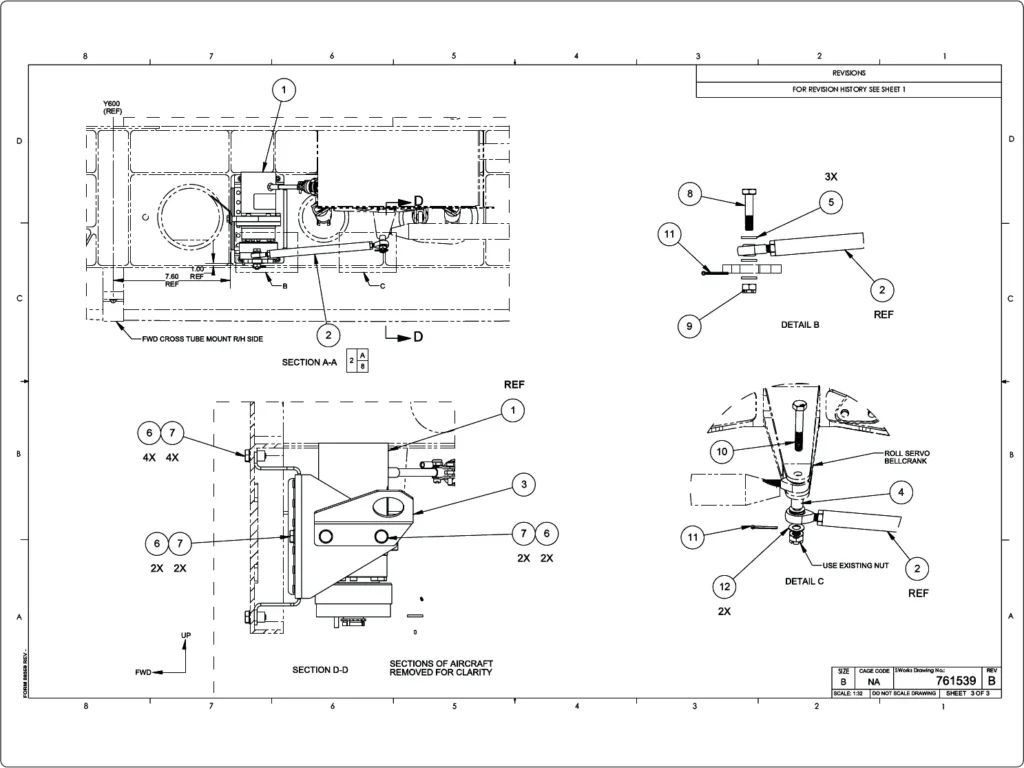
An assembly drawing is usually more complex than a detail drawing and is often accompanied by detail drawings of the individual parts. Figure 4 illustrates an example of an assembly drawing.

Installation Drawing
An installation drawing provides the necessary information for a part or assembly in its final installed position in the aircraft. It shows the dimensions required to locate specific parts in relation to other components and may include reference dimensions that are useful for subsequent maintenance or repair work in the shop. Figure 5 illustrates an example of an installation drawing.
Sectional View Drawings
A sectional view is obtained by imagining an object cut through at a particular location to reveal its internal shape and construction. The surfaces exposed by the imaginary cut are represented using section lines, also known as crosshatching.
Sectional views help reveal internal features that may be difficult to understand from exterior views alone. The following are common types of sectional views.
Full Section
A full section view is used when the internal construction or hidden features of an object cannot be shown clearly in exterior views. The cutting plane passes completely through the object, and the portion between the observer and the cutting plane is considered removed.
The exposed surfaces are represented using section lines. For example, Figure 6 shows a sectional view of a cable connector, illustrating its internal construction.

Half Section
In a half section, the cutting plane extends only halfway through the object, leaving one half represented as an exterior view and the other half as a sectional view.
Half sections are commonly used with symmetrical objects to show both their interior and exterior features in a single view. Figure 7 illustrates a half-sectional view of a capstan servo.

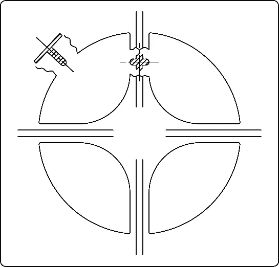
Revolved Section
A revolved section is a cross-sectional view drawn directly on an exterior view of an object. It shows the shape of the cross section at a particular location.
Revolved sections are useful for illustrating the cross-sectional shape of components such as the spokes of a wheel. Figure 8 illustrates an example of a revolved section.
Removed Section
A removed section illustrates the cross-sectional shape of an object at a specific location. Unlike a revolved section, it is drawn separately from the principal view and placed to one side.
Removed sections may be drawn at a larger scale than the principal view to show important details more clearly. The cutting plane location is identified on the principal view, and the corresponding section is labeled appropriately.
Figure 9 illustrates removed sections. Section A-A shows the cross-sectional shape of the object at cutting plane A-A, while Section B-B shows the cross-sectional shape at cutting plane B-B. These sections are drawn at the same scale as the principal view in this example.