
Aircraft air conditioning systems are designed to maintain a comfortable and safe cabin environment by controlling temperature, airflow, and humidity during flight and on the ground. Modern aircraft use either air cycle systems, which are common on turbine-powered aircraft, or vapor cycle systems, which are typically found on reciprocating-engine aircraft. Understanding how these systems cool and condition cabin air is important for aircraft maintenance technicians and pilots because they are closely integrated with the aircraft pneumatic, pressurization, and environmental control systems.
There are two types of air conditioning systems commonly used on aircraft. Air cycle air conditioning is used on most turbine-powered aircraft. It makes use of engine bleed air or APU pneumatic air during the conditioning process. Vapor cycle air conditioning systems are often used on reciprocating aircraft. This type system is similar to that found in homes and automobiles. Note that some turbine-powered aircraft also use vapor cycle air conditioning.
Table of Contents
Table of Contents
Air Cycle Air Conditioning
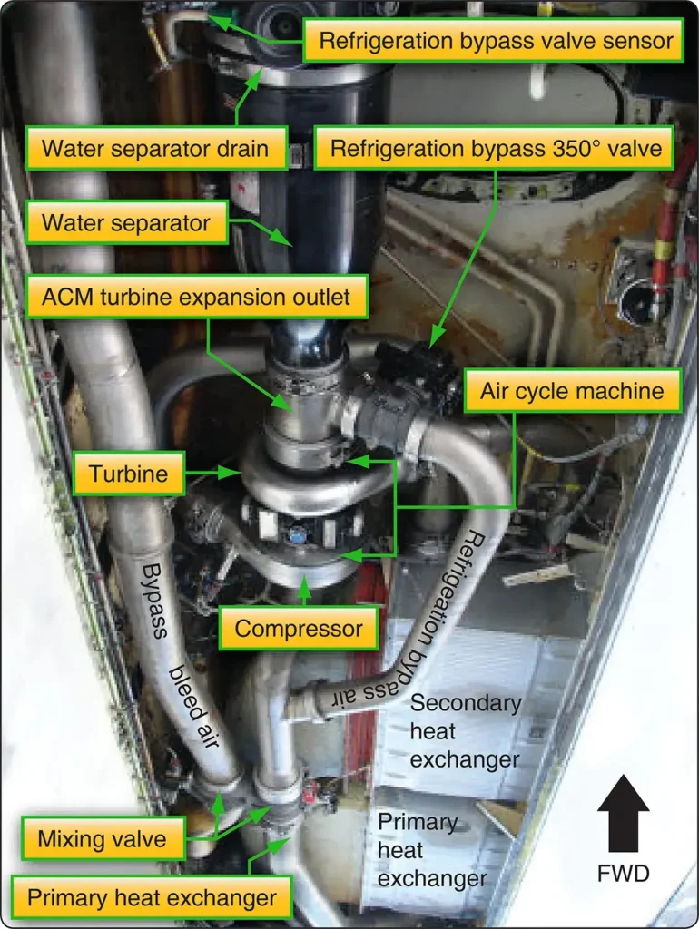
Air cycle air conditioning prepares engine bleed air to pressurize the aircraft cabin. The temperature and quantity of the air must be controlled to maintain a comfortable cabin environment at all altitudes and on the ground. The air cycle system is often called the air conditioning package or pack. It is usually located in the lower half of the fuselage or in the tail section of turbine-powered aircraft. [Figure 1]
System Operation
Even with the frigid temperatures experienced at high altitudes, bleed air is too hot to be used in the cabin without being cooled. It is let into the air cycle system and routed through a heat exchanger where ram air cools the bleed air. This cooled bleed air is directed into an air cycle machine. There, it is compressed before flowing through a secondary heat exchange that cools the air again with ram air. The bleed air then flows back into the air cycle machine where it drives an expansion turbine and cools even further. Water is then removed and the air is mixed with bypassed bleed air for final temperature adjustment. It is sent to the cabin through the air distribution system.
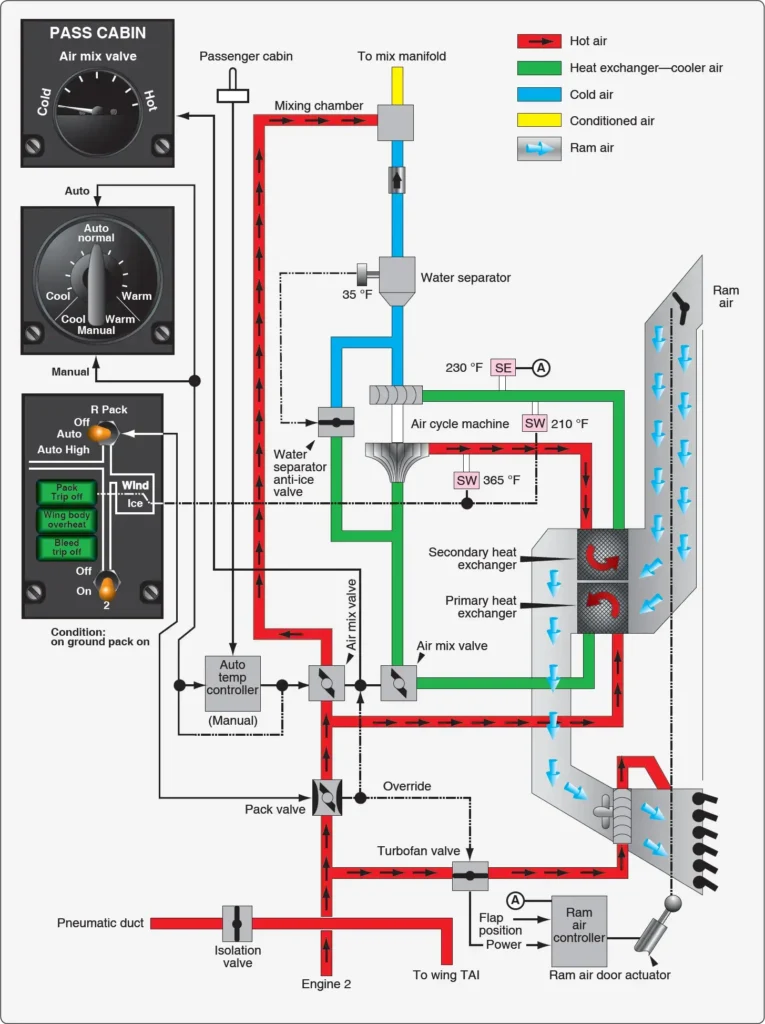
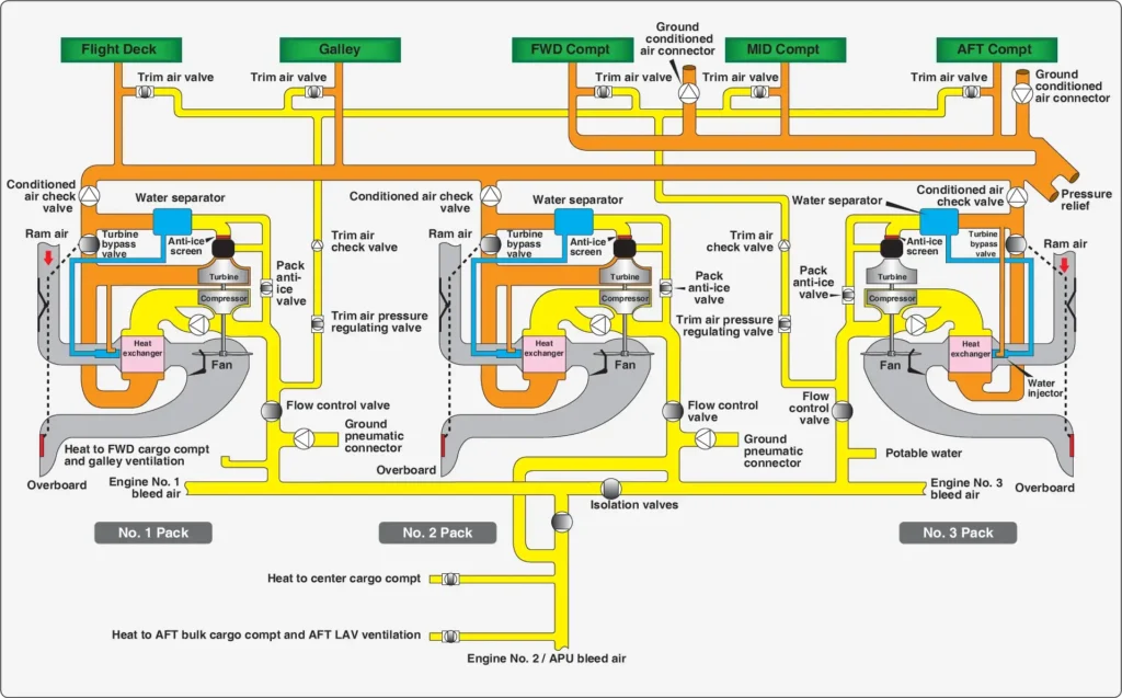
By examining the operation of each component in the air cycle process, a better understanding can be developed of how bleed air is conditioned for cabin use. Refer to Figure 2, which diagrams the air cycle air conditioning system of the Boeing 737.
Pneumatic System Supply
The air cycle air conditioning system is supplied with air by the aircraft pneumatic system. In turn, the pneumatic system is supplied by bleed air tap-offs on each engine compressor section or from the APU pneumatic supply. An external pneumatic air supply source may also be connected while the aircraft is stationary on the ground. In normal flight operations, a pneumatic manifold is supplied by the engine bleed air through the use of valves, regulators, and ducting. The air conditioning packs are supplied by this manifold as are other critical airframe systems, such as the anti-ice and hydraulic pressurization system.
Component Operation
Pack Valve
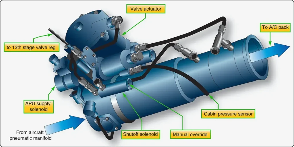
The pack valve is the valve that regulates bleed air from the pneumatic manifold into the air cycle air conditioning system. It is controlled with a switch from the air conditioning panel in the cockpit. Many pack valves are electrically controlled and pneumatically operated. Also known as the supply shutoff valve, the pack valve opens, closes, and modulates to allow the air cycle air conditioning system to be supplied with a designed volume of hot, pressurized air. [Figure 3] When an overheat or other abnormal condition requires that the air conditioning package be shut down, a signal is sent to the pack valve to close.
Bleed Air Bypass
A means for bypassing some of the pneumatic air supplied to the air cycle air conditioning system around the system is present on all aircraft. This warm bypassed air must be mixed with the cold air produced by the air cycle system so the air delivered to the cabin is a comfortable temperature. It simultaneously controls the flow of bypassed air and air to be cooled to meet the requirements of the auto temperature controller. It can also be controlled manually with the cabin temperature selector in manual mode. Other air cycle systems may refer to the valve that controls the air bypassed around the air cycle cooling system as a temperature control valve, trim air pressure regulating valve, or something similar.
Primary Heat Exchanger
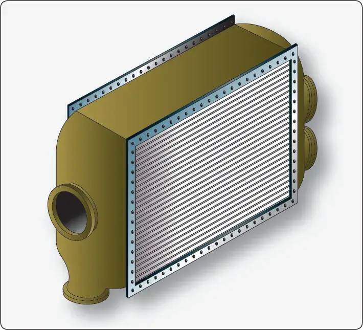
Generally, the warm air dedicated to pass through the air cycle system first passes through a primary heat exchanger. It acts similarly to the radiator in an automobile. A controlled flow of ram air is ducted over and through the exchanger, which reduces the temperature of the air inside the system. [Figure 4]
A fan draws air through the ram air duct when the aircraft is on the ground so that the heat exchange is possible when the aircraft is stationary. In flight, ram air doors are modulated to increase or decrease ram air flow to the exchanger according to the position of the wing flaps. During slow flight, when the flaps are extended, the doors are open. At higher speeds, with the flaps retracted, the doors move toward the closed position reducing the amount of ram air to the exchanger. Similar operation is accomplished with a valve on smaller aircraft. [Figure 5]
Refrigeration Turbine Unit or Air Cycle Machine and Secondary Heat Exchanger
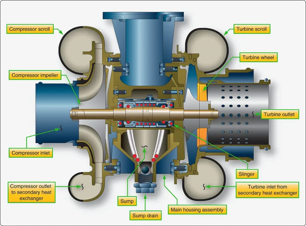
The heart of the air cycle air conditioning system is the refrigeration turbine unit, also known as the air cycle machine (ACM). It is comprised of a compressor that is driven by a turbine on a common shaft. System air flows from the primary heat exchanger into the compressor side of the ACM. As the air is compressed, its temperature rises. It is then sent to a secondary heat exchanger, similar to the primary heat exchanger located in the ram air duct. The elevated temperature of the ACM compressed air facilitates an easy exchange of heat energy to the ram air.
The cooled system air, still under pressure from the continuous system air flow and the ACM compressor, exits the secondary heat exchanger. It is directed into the turbine side of the ACM. The steep blade pitch angle of the ACM turbine extracts more energy from the air as it passes through and drives the turbine. Once through, the air is allowed to expand at the ACM outlet, cooling even further. The combined energy loss from the air first driving the turbine and then expanding at the turbine outlet lowers the system air temperature to near freezing. [Figure 6]
Water Separator
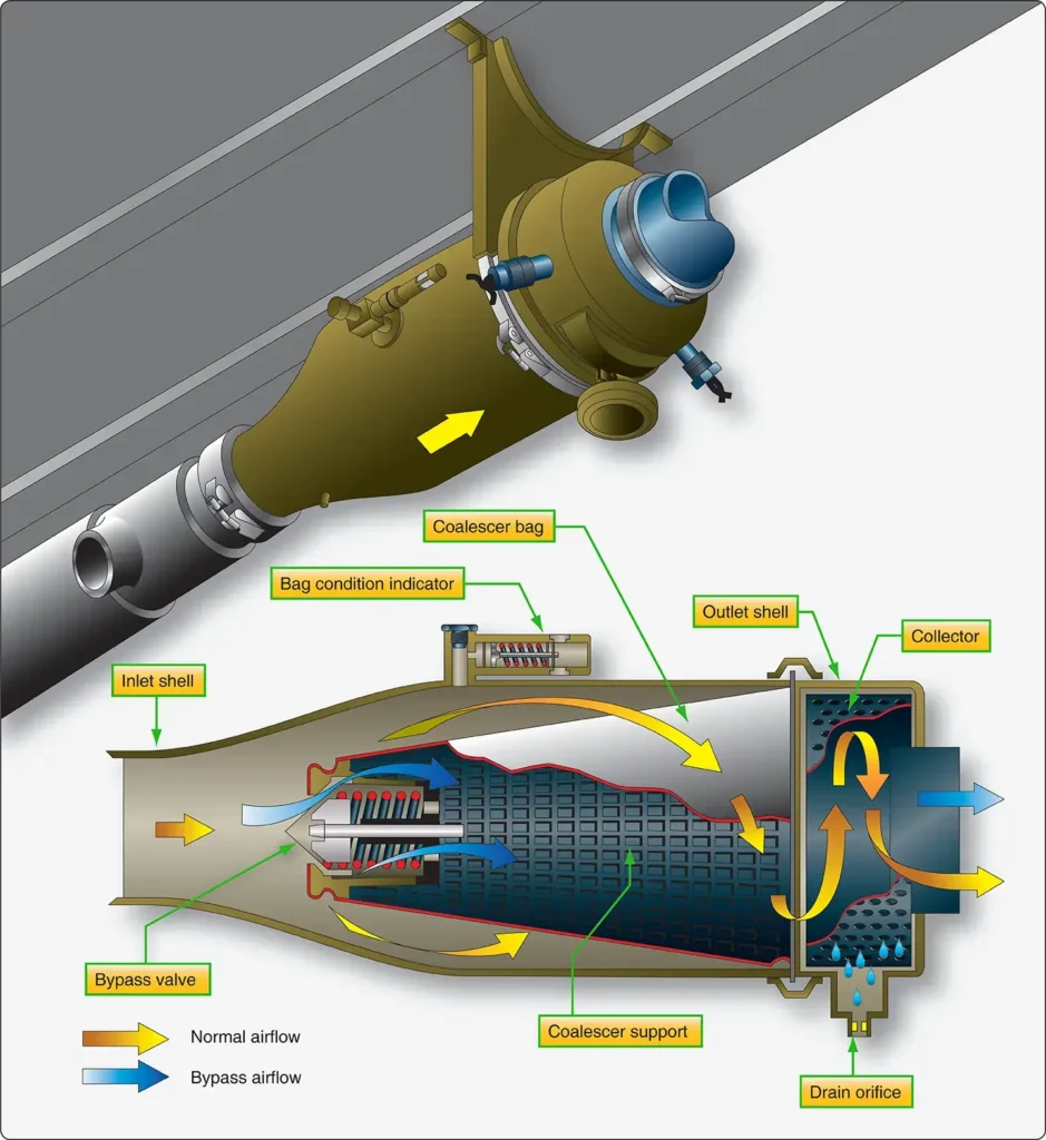
The cool air from the air cycle machine can no longer hold the quantity of water it could when it was warm. A water separator is used to remove the water from the saturated air before it is sent to the aircraft cabin. The separator operates with no moving parts. Foggy air from the ACM enters and is forced through a fiberglass sock that condenses and coalesces the mist into larger water drops. The convoluted interior structure of the separator swirls the air and water. The water collects on the sides of the separator and drains down and out of the unit, while the dry air passes through. A bypass valve is incorporated in case of a blockage. [Figure 7]
Refrigeration Bypass Valve
As mentioned, air exiting the ACM turbine expands and cools. It becomes so cold, it could freeze the water in the water separator, thus inhibiting or blocking airflow. A temperature sensor in the separator controls a refrigeration bypass valve designed to keep the air flowing through the water separator above freezing temperature.
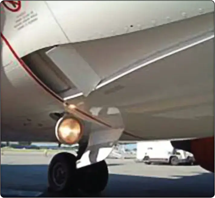
The valve is also identified by other names such as a temperature control valve, 35° valve, anti-ice valve, and similar. It bypasses warm air around the ACM when opened. The air is introduced into the expansion ducting, just upstream of the water separator, where it heats the air just enough to keep it from freezing. Thus, the refrigeration bypass valve regulates the temperature of the ACM discharge air so it does not freeze when passing through the water separator. This valve is visible in Figure 1 and is diagrammed in the system in Figure 2.
All air cycle air conditioning systems use at least one ram air heat exchanger and an air cycle machine with expansion turbine to remove heat energy from the bleed air, but variations exist. An example of a system different from that described above is found on the McDonnell Douglas DC-10.
Bleed air from the pneumatic manifold is compressed by the air cycle machine compressor before it flows to a single heat exchanger. Condensed water from the water separator is sprayed into the ram air at its entrance to the exchanger to draw additional heat from the compressed bleed air as the water evaporates. A trim air valve for each cabin zone mixes bypassed bleed air with conditioned air in response to individual temperature selectors for each zone. When cooling air demands are low, a turbine bypass valve routes some heat exchanger air directly to the conditioned air manifold. [Figure 8]
Cabin Temperature Control System
Typical System Operation
Most cabin temperature control systems operate in a similar manner. Temperature is monitored in the cabin, cockpit, conditioned air ducts, and distribution air ducts. These values are input into a temperature controller, or temperature control regulator, normally located in the electronics bay. A temperature selector in the cockpit can be adjusted to input the desired temperature. [Figure 9]
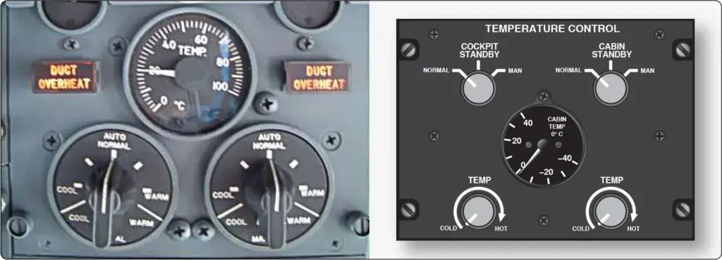
The temperature controller compares the actual temperature signals received from the various sensors with the desired temperature input. Circuit logic for the selected mode processes these input signals. An output signal is sent to a valve in the air cycle air conditioning system. This valve has different names depending on the aircraft manufacturer and design of the environmental control systems (i.e., mixing valve, temperature control valve, trim air valve). It mixes warm bleed air that bypassed the air cycle cooling process with the cold air produced by it. By modulating the valve in response to the signal from the temperature controller, air of the selected temperature is sent to the cabin through the air distribution system.
Cabin temperature pickup units and duct temperature sensors used in the temperature control system are thermistors. Their resistance changes as temperature changes. The temperature selector is a rheostat that varies its resistance as the knob is turned. In the temperature controller, resistances are compared in a bridge circuit. The bridge output feeds a temperature regulating function. An electric signal output is prepared and sent to the valve that mixes hot and cold air.
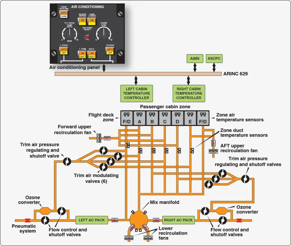
On large aircraft with separate temperature zones, trim air modulating valves for each zone are used. The valves modulate to provide the correct mix required to match the selected temperature. Cabin, flight deck, and duct temperature sensors are strategically located to provide useful information to control cabin temperature. [Figure 10]
Vapor Cycle Air Conditioning
The absence of a bleed air source on reciprocating engine aircraft makes the use of an air cycle system impractical for conditioning cabin air. Vapor cycle air conditioning is used on most non-turbine aircraft that are equipped with air conditioning. However, it is not a source of pressurizing air, as conditioned air from the air cycle system is on turbine-powered aircraft. The vapor cycle system only cools the cabin. If an aircraft equipped with a vapor cycle air conditioning system is pressurized, it uses one of the sources discussed in the pressurization section above. Vapor cycle air conditioning is a closed system used solely for the transfer of heat from inside the cabin to outside of the cabin. It can operate on the ground and in flight.
Theory of Refrigeration
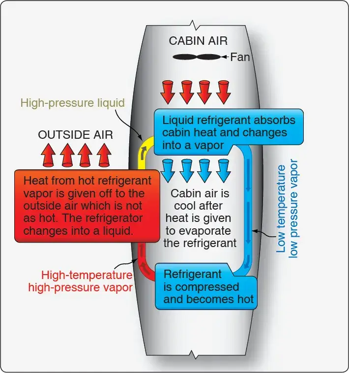
Energy can be neither created nor destroyed; however, it can be transformed and moved. This is what occurs during vapor cycle air conditioning. Heat energy is moved from the cabin air into a liquid refrigerant. Due to the additional energy, the liquid changes into a vapor. The vapor is compressed and becomes very hot. It is removed from the cabin where the very hot vapor refrigerant transfers its heat energy to the outside air. In doing so, the refrigerant cools and condenses back into a liquid. The refrigerant returns to the cabin to repeat the cycle of energy transfer. [Figure 11]
Heat is an expression of energy, typically measured by temperature. The higher the temperature of a substance, the more energy it contains. Heat always flows from hot to cold. These terms express the relative amount of energy present in two substances. They do not measure the absolute amount of heat present. Without a difference in energy levels, there is no transfer of energy (heat).
Adding heat to a substance does not always raise its temperature. When a substance changes state, such as when a liquid changes into a vapor, heat energy is absorbed. This is called latent heat. When a vapor condenses into a liquid, this heat energy is given off. The temperature of a substance remains constant during its change of state. All energy absorbed or given off, the latent heat, is used for the change process. Once the change of state is complete, heat added to a substance raises the temperature of the substance. After a substance changes state into a vapor, the rise in temperature of the vapor caused by the addition of still more heat is called superheat.
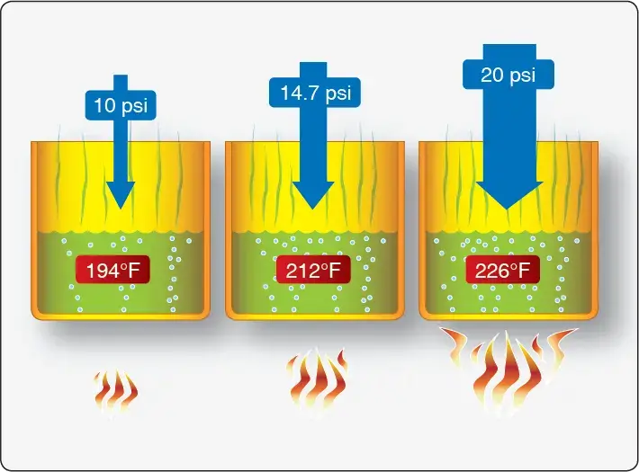
The temperature at which a substance changes from a liquid into a vapor when heat is added is known as its boiling point. This is the same temperature at which a vapor condenses into a liquid when heat is removed. The boiling point of any substance varies directly with pressure. When pressure on a liquid is increased, its boiling point increases, and when pressure on a liquid is decreased, its boiling point also decreases.
For example, water boils at 212 °F at normal atmospheric temperature (14.7 psi). When pressure on liquid water is increased to 20 psi, it does not boil at 212 °F. More energy is required to overcome the increase in pressure. It boils at approximately 226.4 °F. The converse is also true. Water can also boil at a much lower temperature simply by reducing the pressure upon it. With only 10 psi of pressure upon liquid water, it boils at 194 °F. [Figure 12]
Vapor pressure is the pressure of the vapor that exists above a liquid that is in an enclosed container at any given temperature. The vapor pressure developed by various substances is unique to each substance. A substance that is said to be volatile, develops high vapor pressure at standard day temperature (59 °F). This is because the boiling point of the substance is much lower. The boiling point of tetrafluoroethane (R134a), the refrigerant used in most aircraft vapor cycle air conditioning systems, is approximately –15 °F. Its vapor pressure at 59 °F is about 71 psi. The vapor pressure of any substance varies directly with temperature.
Basic Vapor Cycle
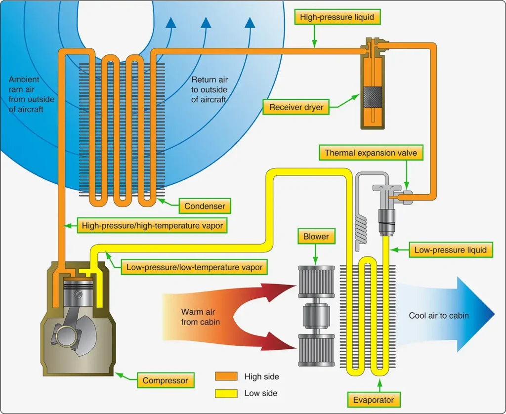
Vapor cycle air conditioning is a closed system in which a refrigerant is circulated through tubing and a variety of components. The purpose is to remove heat from the aircraft cabin. While circulating, the refrigerant changes state. By manipulating the latent heat required to do so, hot air is replaced with cool air in the aircraft cabin.
To begin, R134a is filtered and stored under pressure in a reservoir known as a receiver dryer. The refrigerant is in liquid form. It flows from the receiver dryer through tubing to an expansion valve. Inside the valve, a restriction in the form of a small orifice blocks most of the refrigerant. Since it is under pressure, some of the refrigerant is forced through the orifice. It emerges as a spray of tiny droplets in the tubing downstream of the valve.
The tubing is coiled into a radiator type assembly known as an evaporator. A fan is positioned to blow cabin air over the surface of the evaporator. As it does, the heat in the cabin air is absorbed by the refrigerant, which uses it to change state from a liquid to a vapor. So much heat is absorbed that the cabin air blown by the fan across the evaporator cools significantly. This is the vapor cycle conditioned air that lowers the temperature in the cabin.
The gaseous refrigerant exiting the evaporator is drawn into a compressor. There, the pressure and the temperature of the refrigerant are increased. The high-pressure high-temperature gaseous refrigerant flows through tubing to a condenser. The condenser is like a radiator comprised of a great length of tubing with fins attached to promote heat transfer.
Outside air is directed over the condenser. The temperature of the refrigerant inside is higher than the ambient air temperature, so heat is transferred from the refrigerant to the outside air. The amount of heat given off is enough to cool the refrigerant and to condense it back to a high-pressure liquid. It flows through tubing and back into the receiver dryer, completing the vapor cycle.
There are two sides to the vapor cycle air conditioning system. One accepts heat and is known as the low side. The other gives up heat and is known as the high side. The low and high refer to the temperature and pressure of the refrigerant. As such, the compressor and the expansion valve are the two components that separate the low side from the high side of the cycle. [Figure 13] Refrigerant on the low side is characterized as having low pressure and temperature. Refrigerant on the high side has high pressure and temperature.
Vapor Cycle Air Conditioning System Components
By examining each component in the vapor cycle air conditioning system, greater insight into its function can be gained.
Refrigerant
For many years, dichlorodifluoromethane (R12) was the standard refrigerant used in aircraft vapor cycle air conditioning systems. Some of these systems remain in use today. R12 was found to have a negative effect on the environment; in particular, it degraded the earth’s protective ozone layer. In most cases, it has been replaced by tetrafluoroethane (R134a), which is safer for the environment.
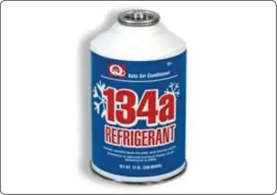
R12 and R134a should not be mixed, nor should one be used in a system designed for the other. Possible damage to soft components, such as hoses and seals, could result causing leaks and/or malfunction. Use only the specified refrigerant when servicing vapor cycle air conditioning systems. [Figure 14]
R12 and R134a behave so similarly that the descriptions of the R134a vapor cycle air conditioning system and components in the following paragraphs also apply to an R12 system and its components.
R134a is a halogen compound (CF3CFH2). As mentioned, it has a boiling point of approximately –15 °F. It is not poisonous to inhale in small quantities, but it does displace oxygen. Suffocation is possible if breathed in mass quantity.
Regardless of manufacturer, refrigerants are sometimes called Freon®, which is a trade name owned by the DuPont Company. Caution should be used when handling any refrigerant. Because of the low boiling points, liquid refrigerants boil violently at typical atmospheric temperatures and pressures. They rapidly absorb heat energy from all surrounding matter. If a drop lands on skin, it freezes, resulting in a burn. Similar tissue damage can result if a drop gets in one’s eye. Gloves and other skin protection, as well as safety goggles, are required when working with refrigerant.
Receiver Dryer
The receiver dryer acts as the reservoir of the vapor cycle system. It is located downstream of the condenser and upstream of the expansion valve. When it is very hot, more refrigerant is used by the system than when temperatures are moderate. Extra refrigerant is stored in the receiver dryer for this purpose.
Liquid refrigerant from the condenser flows into the receiver dryer. Inside, it passes through filters and a desiccant material. The filters remove any foreign particles that might be in the system. The desiccant captures any water in the refrigerant.
Water in the refrigerant causes two major problems. First, the refrigerant and water combine to form an acid. If left in contact with the inside of the components and tubing, the acid deteriorates the materials from which these are made. The second problem with water is that it could form ice and block the flow of refrigerant around the system, rendering it inoperative. Ice is particularly a problem if it forms at the orifice in the expansion valve, which is the coldest point in the cycle.
Occasionally, vapor may find its way into the receiver dryer, such as when the gaseous refrigerant does not completely change state to a liquid in the condenser. A stand tube is used to remove refrigerant from the receiver dryer. It runs to the bottom of the unit to ensure liquid is withdrawn and forwarded to the expansion valve. At the top of the stand tube, a sight glass allows the technician to see the refrigerant.
When enough refrigerant is present in the system, liquid flows in the sight glass. If low on refrigerant, any vapor present in the receiver dryer may be sucked up the stand tube causing bubbles to be visible in the sight glass. Therefore, bubbles in the sight glass indicate that the system needs to have more refrigerant added. [Figure 15]

Expansion Valve
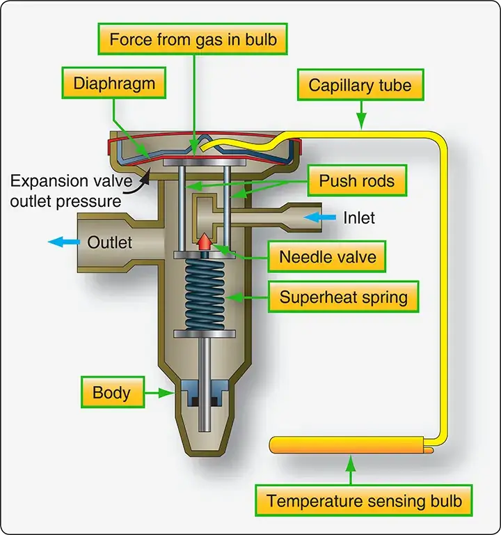
Refrigerant exits the receiver dryer and flows to the expansion valve. The thermostatic expansion valve has an adjustable orifice through which the correct amount of refrigerant is metered to obtain optimal cooling. This is accomplished by monitoring the temperature of the gaseous refrigerant at the outlet of the next component in the cycle, the evaporator. Ideally, the expansion valve should only let the amount of refrigerant spray into the evaporator that can be completely converted to a vapor.
The temperature of the cabin air to be cooled determines the amount of refrigerant the expansion valve should spray into the evaporator. Only so much is needed to completely change the state of the refrigerant from a liquid to a vapor. Too little causes the gaseous refrigerant to be superheated by the time it exits the evaporator. This is inefficient.
Changing the state of the refrigerant from liquid to vapor absorbs much more heat than adding heat to already converted vapor (superheat). The cabin air blowing over the evaporator will not be cooled sufficiently if superheated vapor is flowing through the evaporator. If too much refrigerant is released by the expansion valve into the evaporator, some of it remains liquid when it exits the evaporator. Since it next flows to the compressor, this could be dangerous. The compressor is designed to compress only vapor. If liquid is drawn in and attempts are made to compress it, the compressor could break, since liquids are essentially incompressible.
The temperature of superheated vapor is higher than liquid refrigerant that has not totally vaporized. A coiled capillary tube with a volatile substance inside is located at the evaporator outlet to sense this difference. Its internal pressure increases and decreases as temperature changes. The coiled end of the tube is closed and attached to the evaporator outlet. The other end terminates in the area above a pressure diaphragm in the expansion valve.
When superheated refrigerant vapor reaches the coiled end of the tube, its elevated temperature increases the pressure inside the tube and in the space above the diaphragm. This increase in pressure causes the diaphragm to overcome spring tension in the valve. It positions a needle valve that increases the amount of refrigerant released by the valve. The quantity of refrigerant is increased so that the refrigerant only just evaporates, and the refrigerant vapor does not superheat.
When too much liquid refrigerant is released by the expansion valve, low-temperature liquid refrigerant arrives at the outlet of the evaporator. The result is low pressure inside the temperature bulb and above the expansion valve diaphragm. The superheat spring in the valve moves the needle valve toward the closed position, reducing the flow of refrigerant into the evaporator as the spring overcomes the lower pressure above the diaphragm. [Figure 16]
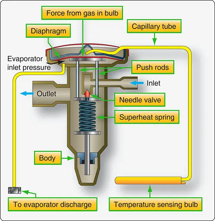
Vapor cycle air conditioning systems that have large evaporators experience significant pressure drops while refrigerant is flowing through them. Externally equalized expansion valves use a pressure tap from the outlet of the evaporator to help the superheat spring balance the diaphragm.
This type of expansion valve is easily recognizable by the additional small-diameter line that comes from the evaporator into the valve (2 total). Better control of the proper amount of refrigerant allowed through the valve is attained by considering both the temperature and pressure of the evaporator refrigerant. [Figure 17]
Evaporator
Most evaporators are constructed of copper or aluminum tubing coiled into a compact unit. Fins are attached to increase surface area, facilitating rapid heat transfer between the cabin air blown over the outside of the evaporator with a fan and the refrigerant inside. The expansion valve located at the evaporator inlet releases high-pressure, high-temperature liquid refrigerant into the evaporator.
As the refrigerant absorbs heat from the cabin air, it changes into a low-pressure vapor. This is discharged from the evaporator outlet to the next component in the vapor cycle system, the compressor. The temperature and pressure pickups that regulate the expansion valve are located at the evaporator outlet.
The evaporator is situated in such a way that cabin air is pulled to it by a fan. The fan blows the air over the evaporator and discharges the cooled air back into the cabin. [Figure 18]
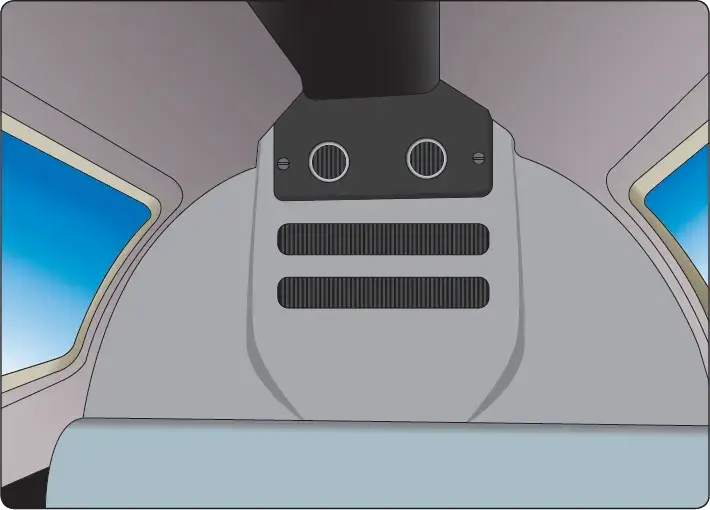
This discharge can be direct when the evaporator is located in a cabin wall. A remotely located evaporator may require ducting from the cabin to the evaporator and from the evaporator back into the cabin. Sometimes the cool air produced may be introduced into an air distribution system where it can blow directly on the occupants through individual delivery vents.
In this manner, the entire vapor cycle air conditioning system may be located fore or aft of the cabin. A multi-position fan switch controlled by the pilot is usually available. Figure 19 diagrams the vapor cycle air conditioning system in a Cessna Mustang very light jet.
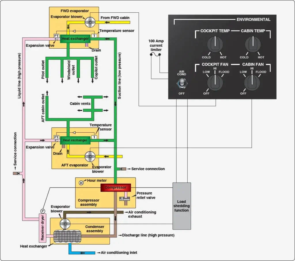
It has two evaporators that share in the cooling, with outlets integrated into a distribution system and cockpit mounted switches for the fans, as well as engaging and disengaging the system.
When cabin air is cooled by flowing over the evaporator, it can no longer retain the water that it could at higher temperature. As a result, it condenses on the outside of the evaporator and needs to be collected and drained overboard. Pressurized aircraft may contain a valve in the evaporator drain line that opens only periodically to discharge the water, to maintain pressurization. Fins on the evaporator must be kept from being damaged, which could inhibit airflow. The continuous movement of warm cabin air around the fins keeps condensed water from freezing. Ice on the evaporator reduces the efficiency of the heat exchange to the refrigerant.
Compressor
The compressor is the heart of the vapor cycle air conditioning system. It circulates the refrigerant around the vapor cycle system. It receives low-pressure, low-temperature refrigerant vapor from the outlet of the evaporator and compresses it. As the pressure is increased, the temperature also increases. The refrigerant temperature is raised above that of the outside air temperature. The refrigerant then flows out of the compressor to the condenser where it gives off the heat to the outside air.
The compressor is the dividing point between the low side and the high side of the vapor cycle system. Often it is incorporated with fittings or has fittings in the connecting lines to it that are designed to service the system with refrigerant. Access to the low and high sides of the system are required for servicing, which can be accomplished with fitting upstream and downstream of the compressor.
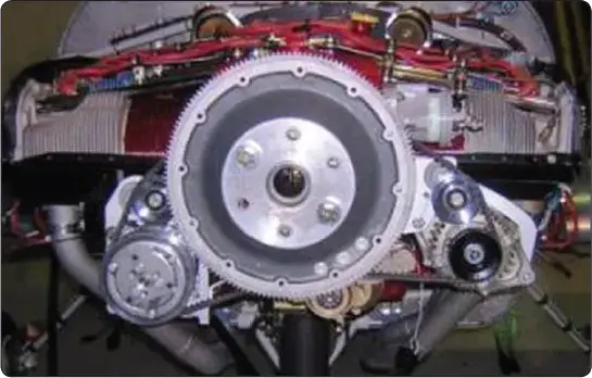
Modern compressors are either engine driven or driven by an electric motor. Occasionally, a hydraulically driven compressor is used. A typical engine-driven compressor, similar to that found in an automobile, is located in the engine nacelle and operated by a drive belt off of the engine crankshaft. An electromagnetic clutch engages when cooling is required, which causes the compressor to operate. When cooling is sufficient, power to the clutch is cut, and the drive pulley rotates but the compressor does not. [Figure 20]
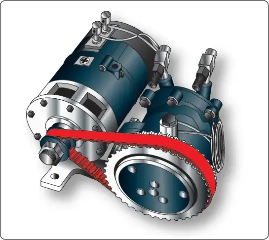
Dedicated electric motor-driven compressors are also used on aircraft. Use of an electric motor allows the compressor to be located nearly anywhere on the aircraft, since wires can be run from the appropriate bus to the control panel and to the compressor. [Figure 21]
Hydraulically driven compressors are also able to be remotely located. Hydraulic lines from the hydraulic manifold are run through a switch activated solenoid to the compressor. The solenoid allows fluid to the compressor or bypasses it. This controls the operation of the hydraulically driven compressor.
Regardless of how the vapor cycle air conditioning compressor is driven, it is usually a piston type pump. It requires use of a lightweight oil to lubricate and seal the unit. The oil is entrained by the refrigerant and circulates with it around the system. The crankcase of the compressor retains a supply of the oil, the level of which can be checked and adjusted by the technician. Valves exist on some compressor installations that can be closed to isolate the compressor from the remainder of the vapor cycle system while oil servicing takes place.
Condenser
The condenser is the final component in the vapor cycle. It is a radiator-like heat exchanger situated so that outside air flows over it and absorbs heat from the high-pressure, high temperature refrigerant received from the compressor. A fan is usually included to draw the air through the compressor during ground operation.
On some aircraft, outside air is ducted to the compressor. On others, the condenser is lowered into the airstream from the fuselage via a hinged panel. Often, the panel is controlled by a switch on the throttle levers. It is set to retract the compressor and streamline the fuselage when full power is required. [Figure 22]
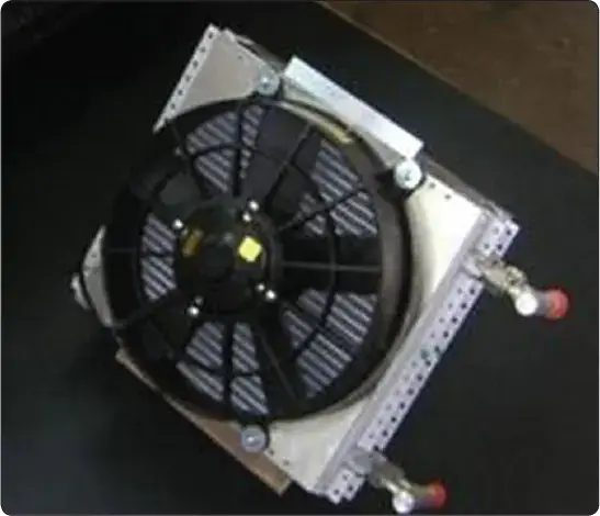
The outside air absorbs heat from the refrigerant flowing through the condenser. The heat loss causes the refrigerant to change state back into a liquid. The high-pressure liquid refrigerant then leaves the condenser and flows to the receiver dryer. A properly engineered system that is functioning normally fully condenses all the refrigerant flowing through the condenser.
Service Valves
All vapor cycle air conditioning systems are closed systems; however, access is required for servicing. This is accomplished through the use of two service valves. One valve is located in the high side of the system and the other in the low side. A common type of valve used on vapor cycle systems that operate with R12 refrigerant is the Schrader valve. It is similar to the valve used to inflate tires. [Figure 23]
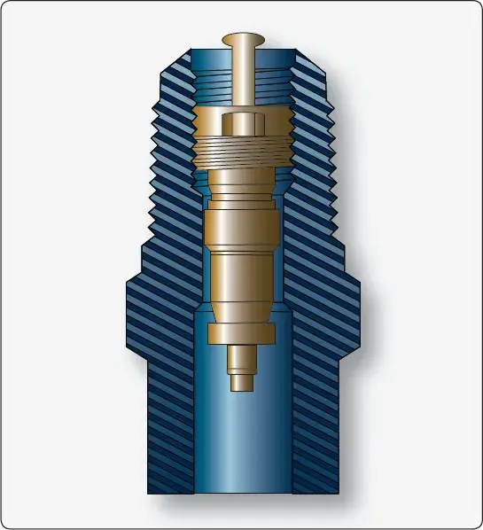
A central valve core seats and unseats by depressing a stem attached to it. A pin in the servicing hose fitting is designed to do this when screwed onto the valve’s exterior threads. All aircraft service valves should be capped when not in use.
R134a systems use valves that are very similar to the Schrader valve in function, operation, and location. As a safety device to prevent inadvertent mixing of refrigerants, R134a valve fittings are different from Schrader valve fittings and do not attach to Schrader valve threads. The R134a valve fittings are a quick-disconnect type.
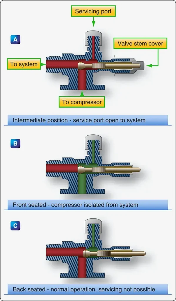
Another type of valve called a compressor isolation valve is used on some aircraft. It serves two purposes. Like the Schrader valve, it permits servicing the system with refrigerant. It also can isolate the compressor so the oil level can be checked and replenished without opening the entire system and losing the refrigerant charge. These valves are usually hard mounted to the inlet and outlet of the compressor.
A compressor isolation valve has three positions. When fully open, it back seats and allows the normal flow of refrigerant in the vapor cycle. When fully closed or front seated, the valve isolates the compressor from the rest of the system and servicing with oil, or even replacement of the compressor, is possible without losing the refrigerant charge. When in an intermediate position, the valve allows access to the system for servicing. The system can be operated with the valve in this position, but should be back seated for normal operation. The valve handle and service port should be capped when servicing is complete. [Figure 24]
Vapor Cycle Air Conditioning Servicing Equipment
Special servicing equipment is used to service vapor cycle air conditioning systems. The U.S. Environmental Protection Agency (EPA) has declared it illegal to release R12 refrigerant into the atmosphere. Equipment has been designed to capture the refrigerant during the servicing process. Although R134a does not have this restriction, it is illegal in some locations to release it to the atmosphere, and it may become universally so in the near future.
It is good practice to capture all refrigerants for future use, rather than to waste them or to harm the environment by releasing them into the atmosphere. Capturing the refrigerant is a simple process designed into the proper servicing equipment. The technician should always be vigilant to use the approved refrigerant for the system being serviced and should follow all manufacturer’s instruction.
Manifold Set, Gauges, Hoses, and Fittings
In the past, the main servicing device for vapor cycle air conditioning systems was the manifold set. It contains three hose fittings, two O-ring sealed valves, and two gauges. It is essentially a manifold into which the gauges, fittings, and valves are attached. The valves are positioned to connect or isolate the center hose with either fitting.
Hoses attach to the right and left manifold set fittings and the other ends of those hoses attach to the service valves in the vapor cycle system. The center fitting also has a hose attached to it. The other end of this hose connects to either a refrigerant supply or a vacuum pump, depending on the servicing function to be performed. All servicing operations are performed by manipulating the valves. [Figure 25]
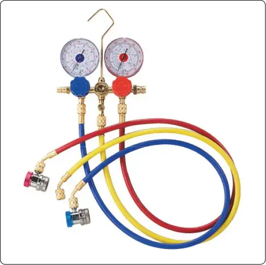
The gauges on the manifold set are dedicated—one for the low side of the system and the other for the high side. The low-pressure gauge is a compound gauge that indicates pressures above or below atmospheric pressure (0 gauge pressure). Below atmospheric pressure, the gauge is scaled in inches of mercury down to 30 inches. This is to indicate vacuum. 29.92 inches equals an absolute vacuum (absolute zero air pressure).
Above atmospheric pressure, gauge pressure is read in psi. The scale typically ranges from 0 to 60 psi, although some gauges extend up to 150 psi. The high-pressure gauge usually has a range from zero up to about 500 psi gauge pressure. It does not indicate vacuum (pressure lower than atmospheric). These gauges and their scales can be seen in Figure 26.
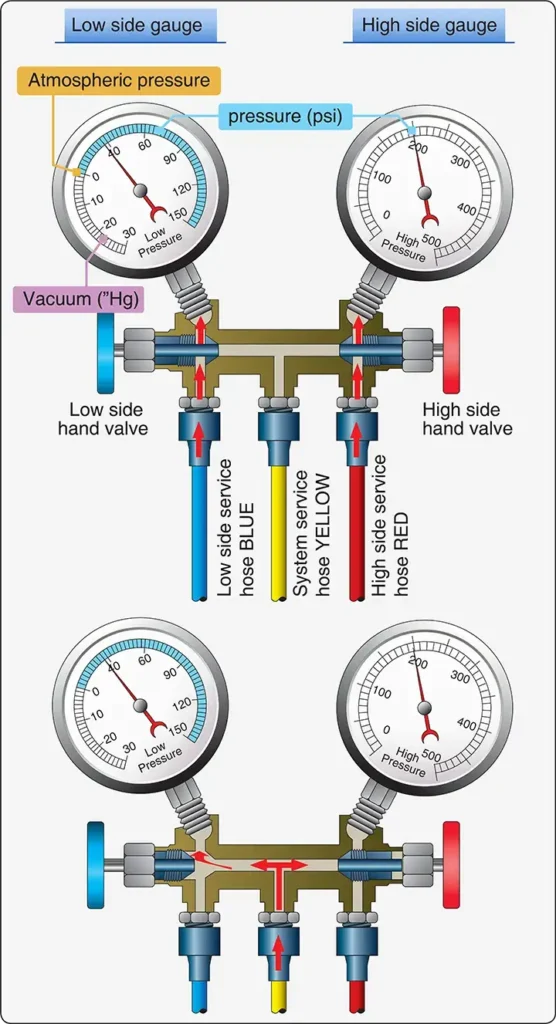
The low-pressure gauge is connected on the manifold directly to the low side fitting. The high-pressure gauge connects directly to the high side fitting. The center fitting of the manifold can be isolated from either of the gauges or the high and low service fittings by the hand valves. When these valves are turned fully clockwise, the center fitting is isolated. If the low-pressure valve is opened (turned counterclockwise), the center fitting is opened to the low pressure gauge and the low side service line. The same is true for the high side when the high-pressure valve is opened. [Figure 26]
Special hoses are attached to the fittings of the manifold valve for servicing the system. The high-pressure charging hose is usually red and attaches to the service valve located in the high side of the system. The low-pressure hose, usually blue, attaches to the service valve that is located in the low side of the system. The center hose attaches to the vacuum pump for evacuating the system, or to the refrigerant supply for charging the system. Proper charging hoses for the refrigerant specific service valves must be used. When not using the manifold set, be sure the hoses are capped to prevent moisture from contaminating the valves.
Full Service Refrigerant Recovery, Recycling, Evacuation, and Recharging Units
Regulations that require capture of all vapor cycle refrigerant have limited the use of the manifold set. It can still be used to charge a system. The refrigerant container is attached to the center hose and the manifold set valves are manipulated to allow flow into the low or high side of the system as required.
But, emptying a system of refrigerant requires a service unit made to collect it. Allowing the refrigerant to flow into a collection container attached to the center hose will not capture the entire refrigerant charge, as the system and container pressures equalize above atmospheric pressure. An independent compressor and collection system is required.
Modern refrigeration recharging and recovery units are available to perform all of the servicing functions required for vapor cycle air conditioning systems. These all-in-one service carts have the manifold set built into the unit. As such, the logic for using a manifold set still applies. Integral solenoid valves, reservoirs, filters, and smart controls allow the entire servicing procedure to be controlled from the unit panel once the high-side and low-side service hoses are connected.
A built-in compressor enables complete system refrigerant purging. A built-in vacuum pump performs system evacuation. A container and recycling filters for the refrigerant and the lubricating oil allow total recovery and recycling of these fluids. The pressure gauges used on the service unit panel are the same as those on a manifold set. Top-of-the-line units have an automatic function that performs all of the servicing functions sequentially and automatically once the hoses are hooked up to the vapor cycle air conditioning system and the system quantity of refrigerant has been entered. [Figure 27]

Refrigerant Source
R134a comes in containers measured by the weight of the refrigerant they hold. Small 12-ounce to 21⁄2-pound cans are common for adding refrigerant. Larger 30- and 50-pound cylinders equipped with shutoff valves are often used to charge an evacuated system, and they are used in shops that service vapor cycle systems frequently. [Figure 28]
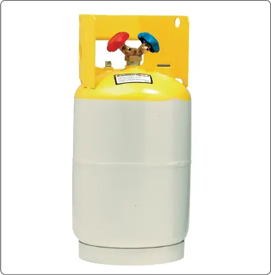
These larger cylinders are also used in the full servicing carts described above. The amount of refrigerant required for any system is measured in pounds. Check the manufacturer’s service data and charge the system to the level specified using only the approved refrigerant from a known source.
Vacuum Pumps
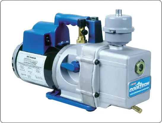
Vacuum pumps used with a manifold set, or as part of a service cart, are connected to the vapor cycle system so that the system pressure can be reduced to a near total vacuum. The reason for doing this is to remove all of the water in the system. As mentioned, water can freeze, causing system malfunction and can also combine with the refrigerant to create corrosive compounds.
Once the system has been purged of its refrigerant and it is at atmospheric pressure, the vacuum pump is operated. It gradually reduces the pressure in the system. As it does, the boiling point of any water in the system is also reduced. Water boils off or is vaporized under the reduced pressure and is pulled from the system by the pump, leaving the system moisture-free to be recharged with refrigerant. [Figure 29]
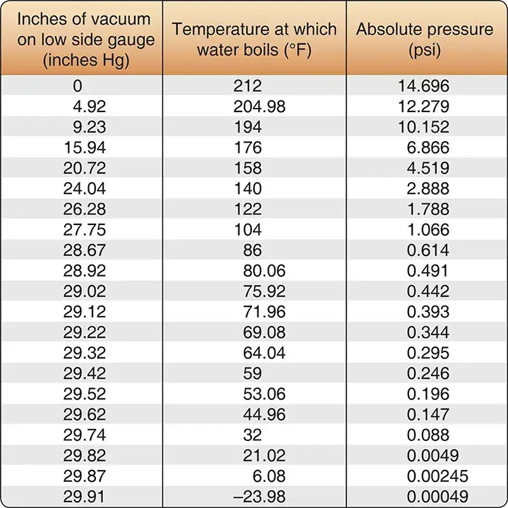
The strength and efficiency of vacuum pumps vary as does the amount of time to hold the system at reduced pressure specified by manufacturers. Generally, the best established vacuum is held for 15–30 minutes to ensure all water is removed from the system. Follow the manufacturer’s instructions when evacuating a vapor cycle air conditioning system. [Figure 30]
Leak Detectors
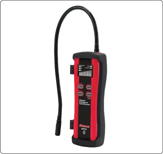
Even the smallest leak in a vapor cycle air conditioning system can cause a loss of refrigerant. When operating normally, little or no refrigerant escapes. A system that requires the addition of refrigerant should be suspected of having a leak. Electronic leak detectors are safe, effective devices used to find leaks.
There are many types available that are able to detect extremely small amounts of escaped refrigerant. The detector is held close to component and hose connections where most leaks occur. Audible and visual alarms signal the presence of refrigerant. A detector specified for the type of refrigerant in the system should be chosen. A good leak detector is sensitive enough to detect leaks that would result in less than 1⁄2 ounce of refrigerant to be lost per year. [Figure 31]
Other leak detection methods exist. A soapy solution can also be applied to fittings and inspected for the formation of bubbles indicating a leak. Special leak detection dyes compatible for use with refrigerant can be injected into the vapor cycle system and can be seen when they are forced out at a leak. Many of these are made to be visible under UV light.
Occasionally, a leak can be detected upon close visual inspection. Oil in the system can be forced out of a leak, leaving a visible residue that is usually on the bottom side of a leaky fitting. Old hoses may become slightly porous and leak a significant amount of refrigerant over time. Because of the length and area through which the refrigerant is lost, this type of leak may be difficult to detect, even with leak detecting methods. Visibly deteriorated hoses should be replaced.
System Servicing
Vapor cycle air conditioning systems can give many hours of reliable, maintenance-free service. Periodic visual inspections, tests, and refrigerant level and oil level checks may be all that is required for some time. Follow the manufacturer’s instructions for inspection criteria and intervals.
Visual Inspection
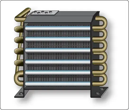
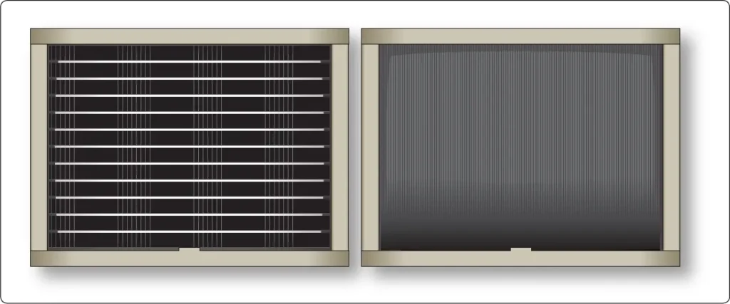
All components of any vapor cycle system should be checked to ensure they are secure. Be vigilant for any damage, misalignment, or visual signs of leakage. The evaporator and condenser fins should be checked to ensure they are clean, unobstructed, and not folded over from an impact. Dirt and inhibited airflow through the fins can prevent effective heat exchange to and from the refrigerant.
Occasionally, these units can be washed. Since the condenser often has ram air ducted to it or extends into the airstream, check for the presence of debris that may restrict airflow. Hinged units should be checked for security and wear. The mechanism to extend and retract the unit should function as specified, including the throttle position switch present on many systems. It is designed to cut power to the compressor clutch and retract the condenser at full power settings. Condensers may also have a fan to pull air over them during ground operation. It should be checked to ensure it functions correctly. [Figure 32]
Be sure the capillary temperature feedback sensor to the expansion valve is securely attached to the evaporator outlet. Also, check the security of the pressure sensor and thermostat sensor if the system has them. The evaporator should not have ice on the outside. This prevents proper heat exchange to the refrigerant from the warm cabin air blown over the unit.
The fan blower should be checked to ensure it rotates freely. Depending on the system, it should run whenever the cooling switch is selected and should change speeds as the selector is rotated to more or less cooling. Sometimes systems low on refrigerant can cause ice on the evaporator, as can a faulty expansion valve or feedback control line. Ice formation anywhere on the outside of a vapor cycle air conditioning system should be investigated for cause and corrected. [Figure 33]
Security and alignment of the compressor is critical and should be checked during inspection. Belt-driven compressors need to have proper belt tension to function properly. Check the manufacturer’s data for information on how to determine the condition and tension of the belt, as well as how to make adjustments. Oil level should be sufficient. Typically, 1⁄4 ounce of oil is added for each pound of refrigerant added to the system. When changing a component, additional oil may need to be added to replace that which is trapped in the replaced unit. Always use the oil specified in the manufacturer’s maintenance manual.
Leak Test
As mentioned under the leak detector section above, leaks in a vapor cycle air conditioning system must be discovered and repaired. The most obvious sign of a possible leak is a low refrigerant level. Bubbles present in the sight glass of the receiver dryer while the system is operating indicate more refrigerant is needed. A system check for a leak may be in order. Note that vapor cycle systems normally lose a small amount of refrigerant each year. No action is needed if this amount is within limits.
Occasionally, all of the refrigerant escapes from the system. No bubbles are visible in the sight glass, but the complete lack of cooling indicates the refrigerant has leaked out. To locate the leak point, the system needs to be partially charged with refrigerant so leak detection methods can be employed.
About 50 psi of refrigerant in the high and low sides should be sufficient for a leak check. By introducing the refrigerant into the high side, pressure indicated on the low side gauge verifies the orifice in the expansion valve is not clogged. When all refrigerant is lost due to a leak, the entire system should be checked. Each fitting and connection should be inspected visually and with a leak detector.
When a vapor cycle air conditioning system loses all of its refrigerant charge, air may enter the system. Water may also enter since it is in the air. This means that a full system evacuation must be performed after the leak is found and repaired. By establishing only a 50 psi charge in a depleted system, the leak(s) become detectable, but time and refrigerant are not wasted prior to evacuation. System evacuation is discussed below.
Performance Test
Verification of proper operation of a vapor cycle air conditioning system is often part of a performance test. This involves operating the system and checking parameters to ensure they are in the normal range. A key indication of system performance is the temperature of the air that is cooled by the evaporator. This can be measured at the air outflow from the evaporator or at a nearby delivery duct outlet.
An ordinary thermometer should read 40–50 °F, with the controls set to full cold after the system has been allowed to operate for a few minutes. Manufacturer’s instructions include information on where to place the thermometer and the temperature range that indicates acceptable performance.
Pressures can also be observed to indicate system performance. Typically, low side pressure in a vapor cycle system operating normally is 10–50 psi, depending on ambient temperature. High side pressure is between 125 and 250 psi, again, depending on ambient temperature and the design of the system. All system performance tests are performed at a specified engine rpm (stable compressor speed) and involve a period of time to stabilize the operation of the vapor cycle. Consult the manufacturer’s instructions for guidance.
Feel Test
A quick reference field test can be performed on a vapor cycle air conditioning system to gauge its health. In particular, components and lines in the high side (from the compressor to the expansion valve) should be warm or hot to the touch. The lines on both sides of the receiver dryer should be the same temperature. Low side lines and the evaporator should be cool. Ice should not be visible on the outside of the system. If any discrepancies exist, further investigation is needed. On hot, humid days, the cooling output of the vapor cycle system may be slightly compromised due to the volume of water condensing on the evaporator.
Purging the System
Purging the system means emptying it of its refrigerant charge. Since the refrigerant must be captured, a service cart with this capability should be used. By connecting the hoses to the high side and low side service valves and selecting recover, cart solenoid valves position so that a system purging compressor pumps the refrigerant out of the vapor cycle system and into a recovery tank.
Vapor cycle systems must be properly purged before opening for maintenance or component replacement. Once opened, precautions should be taken to prevent contaminants from entering the system. When suspicion exists that the system has been contaminated, such as when a component has catastrophically failed, it can be flushed clean. A special flushing fluid formulated for vapor cycle air conditioning systems should be used. The receiver dryer is removed from the system for flushing and a new unit is installed, as it contains fresh filters. Follow the aircraft manufacturer’s instructions.
Checking Compressor Oil
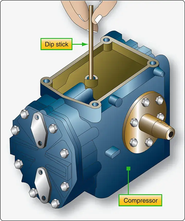
The compressor is a sealed unit in the vapor cycle system that is lubricated with oil. Any time the system is purged, it is an opportunity to check the oil quantity in the compressor crankcase. This is often done by removing a filler plug and using a dipstick. Oil quantity should be maintained within the proper range using oil recommended by the manufacturer. Be certain to replace the filler plug after checking or adding oil. [Figure 34]
Evacuating the System
Only a few drops of moisture can contaminate a vapor cycle air conditioning system. If this moisture freezes in the expansion valve, it could completely block the refrigerant flow. Water is removed from the system by evacuation. Anytime the system refrigerant charge falls below atmospheric pressure, the refrigerant is lost, or the system is opened, it must be evacuated before recharging.
Evacuating a vapor cycle air conditioning system is also known as pumping down the system. A vacuum pump is connected and pressure inside the system is reduced to vaporize any water that may exist. Continued operation of the vacuum pump draws the water vapor from the system. A typical pump used for evacuating an air conditioning system can reduce system pressure to about 29.62 “Hg (gauge pressure). At this pressure, water boils at 45 °F. Operate the vacuum pump to achieve the recommended gauge pressure. Hold this vacuum for as long as the manufacturer specifies.
As long as a vapor cycle air conditioning system retains a charge higher than atmospheric pressure, any leak forces refrigerant out of the system. The system pressure prevents air (and water vapor) from entering. Therefore, it is permissible to recharge or add refrigerant to a system that has not dropped below atmospheric pressure without evacuating the system.
Charging the System
Charging capacity of a vapor cycle air conditioning system is measured by weight. The aircraft manufacturer’s maintenance manual specifies this amount and the amount and type of oil to be put into the system when filling. Preweighing the refrigerant or setting the refrigerant weight into the servicing cart input ensures the system is filled to capacity.
Charging a vapor cycle air conditioning system should be undertaken immediately after evacuation of the system is completed. With the hoses still connected to the high and low side service valves, selecting charge on the service cart panel positions solenoid-operated valves so that the refrigerant supply is available.
First, refrigerant is released into the high side of the system. Observe the low side gauge. When the low side gauge begins to indicate pressure, it is known that refrigerant is passing through the tiny orifice in the expansion valve. As pressure builds in the high side, the flow of refrigerant into the system stops.
To complete the charge of the system, refrigerant needs to be drawn in by the compressor. A major concern is to avoid damage to the compressor by having liquid refrigerant enter the compressor inlet. After the initial release of refrigerant into the high side, the high side service valve is closed and the remaining charge is made through the low side service valve.
The engine is started and run at a specified rpm, usually a high idle speed. Full cool is selected on the air conditioning control panel in the cockpit. As the compressor operates, it draws vapor into the low side until the correct weighed amount of refrigerant is in the system. Charging is completed with a full performance test.
Charging with a manifold set is accomplished in the same way. The manifold center hose is connected to the refrigerant source that charges the system. After opening the valve on the container (or puncturing the seal on a small can), the center hose connection on the manifold set should be loosened to allow air in the hose to escape. Once the air is bled out of the hose, the refrigerant can enter the system through whichever service valve is opened. The sequence is the same as above and all manufacturer instructions should be followed.
Oil quantity added to the system is specified by the manufacturer. Refrigerant premixed with oil is available and may be permissible for use. This eliminates the need to add oil separately. Alternately, the amount of oil to be put into the system can be selected on the servicing cart. Approximately 1⁄4 ounce of oil for each pound of refrigerant is a standard amount; however, follow the manufacturer’s specifications.
Technician Certification
The EPA requires certification of technicians that work with vapor cycle air conditioning refrigerant and equipment to ensure safe compliance with current regulations. Aircraft technicians can obtain certification or can refer vapor cycle air conditioning work to shops that specialize in this work.