
Aircraft oxygen systems are designed to provide an adequate supply of breathing oxygen to pilots, crew members, and passengers when the oxygen available in the surrounding atmosphere is insufficient. These systems vary according to aircraft type, operating altitude, pressurization capability, and the number of occupants who may require oxygen.
Gaseous oxygen systems are commonly used in general aviation and as backup systems in transport aircraft. Other systems use chemical oxygen generators or liquid oxygen (LOX). Oxygen delivery may be continuous-flow or demand-flow, depending on the system design and operational requirements.
An aircraft oxygen system consists of several components, including oxygen storage cylinders, regulators, masks, flow indicators, tubing, fittings, and valves. Understanding the function and operation of these components is essential for proper system operation, inspection, and maintenance.
Table of Contents
Table of Contents
Gaseous Oxygen Systems
Gaseous oxygen systems are widely used in aviation, although their configurations vary considerably.
In a light aircraft, the system may consist of a portable oxygen cylinder with a single mask connected through a hose to a regulator mounted on the cylinder. Larger portable cylinders may use regulators that divide the oxygen supply among two to four users.
Built-in oxygen systems installed in high-performance and light twin-engine aircraft typically have designated locations for oxygen cylinders. The cylinders supply oxygen through tubing and regulators to individual breathing stations. Passengers may connect their masks or hoses to outlets located near their seats.
A central regulator may control the oxygen supply, while the flight crew may have separate regulators or dedicated oxygen supplies. Transport-category aircraft may incorporate a more elaborate gaseous oxygen system as a backup to cabin pressurization.
In these systems, oxygen is stored as a gas at ambient temperature in high-pressure cylinders. It is then distributed through a network of components designed to reduce pressure, control flow, and deliver oxygen to the users.
Oxygen Storage Cylinders
Gaseous oxygen is stored and transported in high-pressure cylinders. Traditionally, these cylinders were constructed from heavy steel and were commonly rated for pressures of approximately 1,800–1,850 psi, with some designs capable of withstanding higher pressures.
To reduce weight, newer cylinders may use a lightweight aluminum liner wrapped with a composite material such as Kevlar®. These cylinders can store oxygen at comparable pressures while weighing considerably less than traditional steel cylinders. Heavy-walled all-aluminum cylinders are also used, particularly as portable oxygen supplies in light aircraft.
Most oxygen cylinders have traditionally been painted green. However, cylinder colors can vary according to applicable standards and jurisdictions, so identification markings and labels must always be checked.
Oxygen cylinders are manufactured and certified to applicable specifications, such as those established by the U.S. Department of Transportation (DOT). To ensure continued serviceability, cylinders must undergo periodic inspections and hydrostatic testing in accordance with their certification requirements. [Figure 1]

Hydrostatic testing generally involves filling the cylinder with water and pressurizing it to a specified test pressure. The cylinder must not leak, rupture, or deform beyond the permitted limits. The applicable test pressure and acceptance criteria depend on the cylinder specification.
Cylinder Types, Certification, and Service Life
Oxygen cylinders have a limited service life. Depending on their specification, they may need to be removed from service after a prescribed number of filling cycles, a specified calendar age, or when they no longer meet inspection requirements.
Common high-pressure steel oxygen cylinders used in aviation include DOT specification 3AA and 3HT cylinders. They are available in different sizes and are subject to their respective certification and service requirements.
Lightweight composite cylinders are also used. Some cylinders previously certified under DOT special permit DOT-E-8162 are now associated with DOT-SP-8162 requirements. Their inspection and hydrostatic test intervals must be determined from the current applicable specification and cylinder markings rather than assumed to be universal. [Figure 2]

The manufacture date and certification information are stamped near the cylinder neck. Subsequent hydrostatic test dates may also be stamped in this area. Composite cylinders may use a label or placard for this information. Any additional markings or updates must be applied in accordance with the applicable requirements.
Minimum Residual Pressure
Oxygen cylinders are commonly considered empty for servicing purposes when their pressure falls below a specified residual pressure. The source material identifies 50 psi as the minimum pressure.
Maintaining residual pressure helps prevent moisture-containing air from entering the cylinder. Moisture can cause internal corrosion and may contribute to ice formation that could restrict a valve or a narrow passage in the oxygen system.
An installed cylinder that has fallen below the specified residual pressure must be handled in accordance with the applicable maintenance instructions. It may require removal, inspection, or other approved servicing before being returned to service.
Oxygen Systems and Regulators
The design of an aircraft oxygen system depends on the aircraft type, operational requirements, and whether the aircraft is pressurized.
Oxygen systems are commonly classified according to how oxygen is delivered to the user. The two principal types are:
- Continuous-flow systems: Oxygen flows continuously at a regulated rate while the system is operating.
- Demand-flow systems: Oxygen is supplied primarily when the user inhales.
Some aircraft use a combination of both systems. Continuous-flow systems are common for passenger oxygen supplies, while demand-flow and pressure-demand systems are widely used for flight crew on high-performance and transport-category aircraft.
Continuous-Flow Systems
In a basic continuous-flow system, oxygen leaves the storage cylinder through a valve and passes through a regulator or pressure reducer. The regulator reduces the high cylinder pressure to a suitable delivery pressure, and the oxygen flows through a hose to the user’s mask.
Once the system is activated, oxygen continues to flow at a preset rate. Flow continues during inhalation, exhalation, and periods when the mask is not being used, unless the supply is shut off. Some systems include an adjustable flow indicator installed in the hose, allowing the user to make limited adjustments to the oxygen flow.
A portable oxygen system used in a light aircraft is an example of a basic continuous-flow system. [Figure 3]

Adjustable Continuous-Flow Regulators
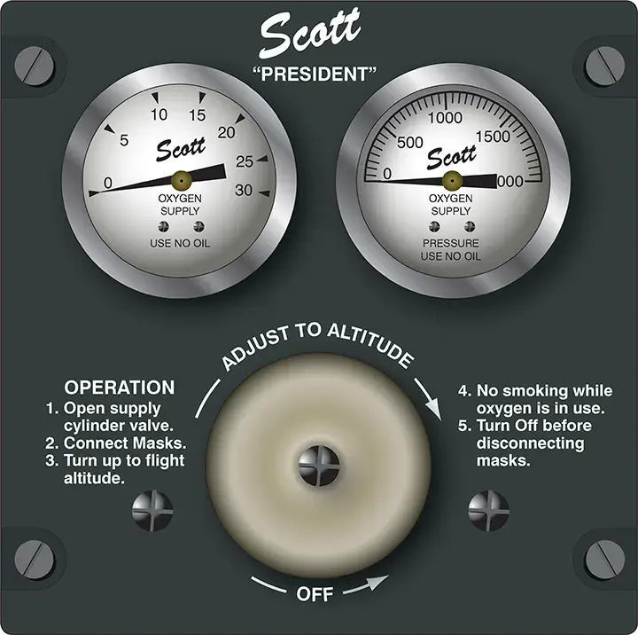
More sophisticated continuous-flow systems use regulators that vary the oxygen flow according to altitude and the user’s requirements.
Manual continuous-flow regulators are adjusted by the crew as altitude changes. Automatic regulators use an aneroid mechanism that responds to changes in ambient pressure. As altitude increases and pressure decreases, the mechanism adjusts the regulator to provide a greater oxygen flow. [Figure 4]
Built-In Continuous-Flow Systems
Many aircraft have permanently installed oxygen cylinders connected to passenger and crew breathing stations through fixed plumbing.
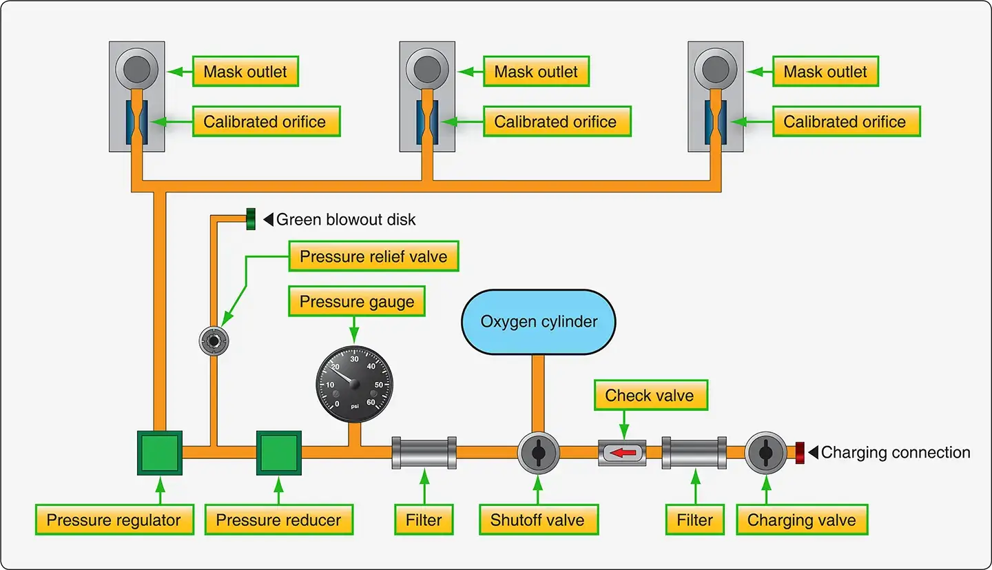
In larger aircraft, separate oxygen supplies may be provided for the flight crew and passengers. Integrated systems typically include remotely mounted pressure-reducing components, regulators, filters, pressure-relief devices, and gauges that indicate the remaining cylinder pressure.
The arrangement of these components varies with the aircraft design. Figure 5 illustrates a typical continuous-flow oxygen system used in small- to medium-sized aircraft.
Oxygen Flow at Individual Stations
Built-in continuous-flow systems often use a calibrated orifice at each user station to establish the final oxygen flow rate. Larger orifices may be used for crew masks to provide a greater flow than passenger masks.
Specialized masks may be designed to provide increased oxygen flow for users with particular medical requirements. Such equipment must be used in accordance with its approved design and instructions.
Rebreather Systems
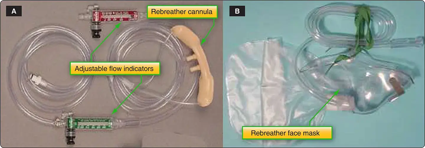
Continuous-flow oxygen systems can consume oxygen inefficiently because oxygen continues to flow during exhalation. Rebreather equipment helps reduce this waste by capturing part of the exhaled oxygen-air mixture for reuse during the next inhalation.
A rebreather bag or oxygen reservoir collects part of the exhaled mixture. The user then inhales the retained gas along with the newly supplied oxygen. This reduces the quantity of oxygen lost to the surrounding environment [Figure 6]
Passenger Oxygen Supply and Mask Deployment
A passenger continuous-flow system may use plug-in oxygen outlets located near the passenger seats. In some systems, oxygen flow is inhibited until the passenger connects the mask or hose to the outlet.
In pressurized aircraft, emergency passenger oxygen masks are commonly stowed in overhead passenger service units (PSUs). When cabin altitude reaches the system’s deployment threshold, the masks may automatically deploy. The flight crew may also be able to initiate deployment manually.
A lanyard attached to the mask may activate the oxygen flow when the mask is pulled down. The actual activation mechanism depends on the system design. [Figure 7]

Emergency passenger oxygen mask deployment may also be controlled by the flight crew through a dedicated control or switch. [Figure 8]

Continuous-Flow Oxygen Masks
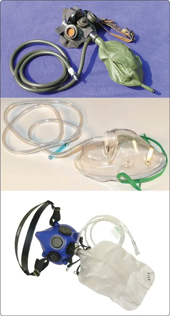
Continuous-flow oxygen masks direct the oxygen-air mixture toward the user’s nose and mouth. They are designed to fit securely but are generally not airtight.
Vent openings allow cabin air to mix with the oxygen and permit exhaled gas to escape. In rebreather masks, the vents also allow the portion of the exhaled mixture that is not retained in the reservoir bag to escape. [Figure 9]
Demand-Flow or Pressure-Demand Systems
In a demand-flow oxygen system, oxygen is supplied primarily when the user inhales. During pauses in breathing and exhalation, the oxygen supply is stopped, reducing waste and extending the duration of the available supply.
Demand-flow systems are commonly used by flight crews in high-performance and transport-category aircraft. [Figure 10]
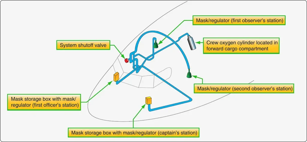
Demand-flow systems share several components with continuous-flow systems. These may include cylinder valves, pressure gauges, filters, pressure-relief valves, pressure reducers, and plumbing. However, the individual oxygen regulators and masks are designed to respond to the user’s breathing. [Figure 11]
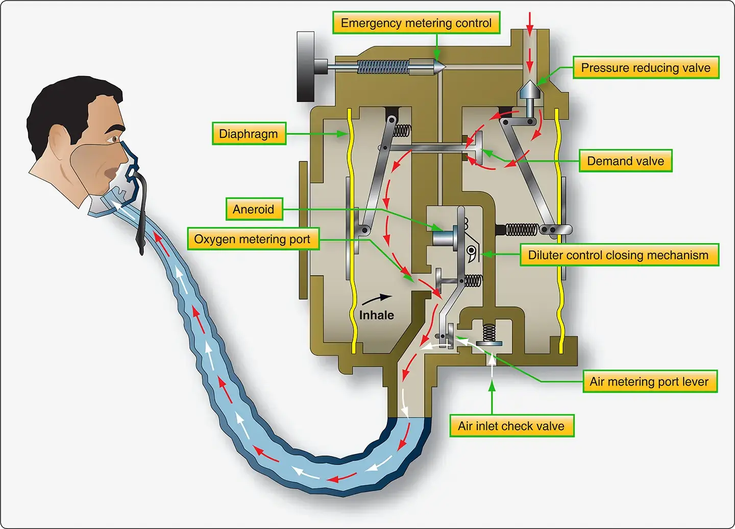
Pressure Reduction and Individual Regulators
In some demand-flow systems, a pressure-reducing valve lowers the cylinder pressure to an intermediate pressure, often in the range of approximately 60–85 psi. The oxygen is then supplied to individual regulators for each user.
A further pressure reduction may occur at the inlet of the individual regulator. [Figure 12] Two common types of individual regulators are:
- Pressure-demand regulators
- Diluter-demand regulators
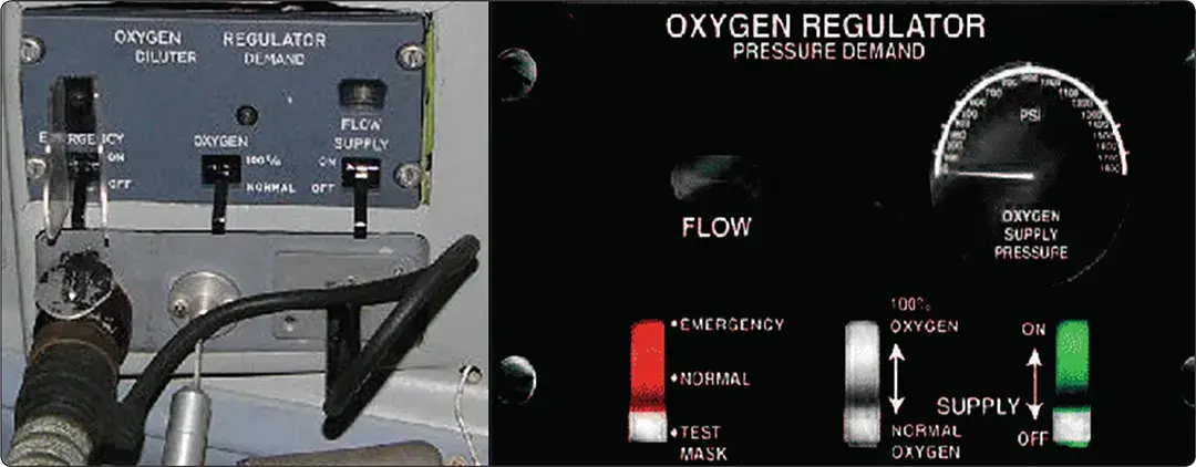
Diluter-Demand Regulators
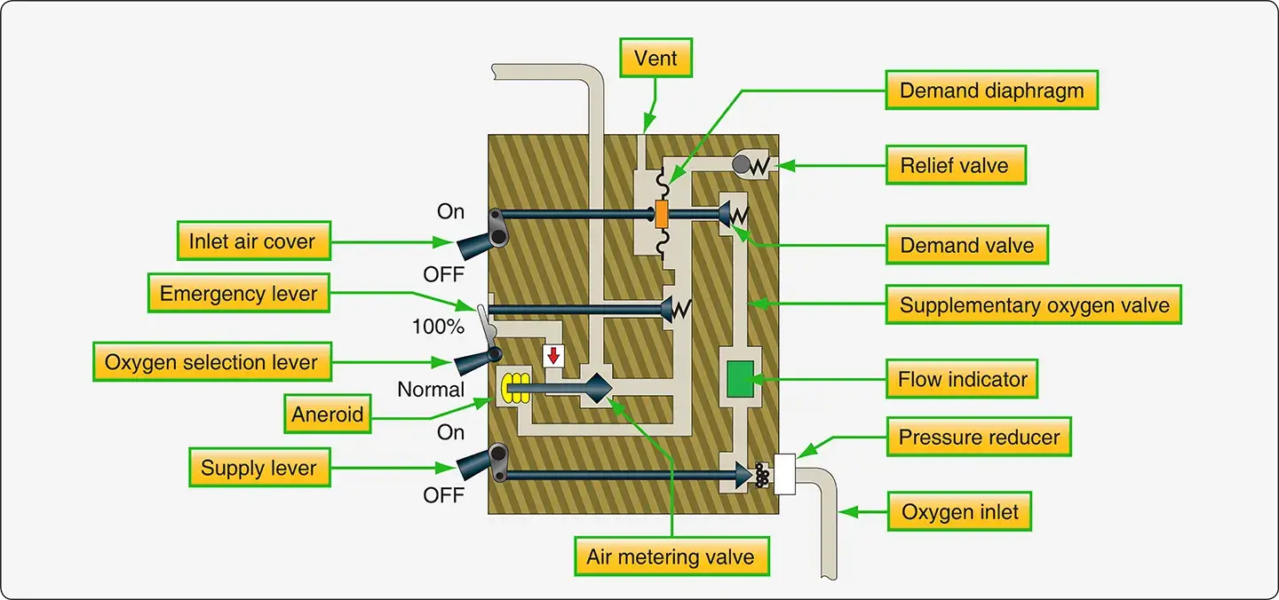
A diluter-demand regulator supplies oxygen when the user inhales through a demand-type mask. During normal operation, the regulator mixes oxygen with cabin air to provide the required breathing mixture.
The amount of dilution depends on cabin altitude. As cabin altitude increases, an aneroid mechanism adjusts the metering valve to provide a greater proportion of oxygen and a smaller proportion of cabin air.
At sufficiently high cabin altitudes, the regulator may supply 100 percent oxygen. The source material identifies approximately 34,000 feet as a typical point at which the regulator may deliver 100 percent oxygen, but the actual operating schedule varies by regulator design.
The user may also select 100 percent oxygen manually. An emergency control may bypass the normal demand function and provide a continuous flow of oxygen, depending on the regulator design. [Figure 13]
Pressure-Demand Regulators
Pressure-demand systems operate similarly to diluter-demand systems, but they deliver oxygen at a pressure above the surrounding pressure during inhalation. This helps maintain an adequate oxygen supply at very high altitudes.
The regulator still responds to the user’s breathing, so oxygen is supplied primarily during inhalation. Depending on the design and operating mode, the system may also dilute oxygen with cabin air at lower cabin altitudes.
Pressure-demand regulators are used in aircraft that operate at very high altitudes, including aircraft that may fly at 40,000 feet and above. They are also installed in some high-performance aircraft and airliners.
Both diluter-demand and pressure-demand regulators may be panel-mounted or mask-mounted. Their operating principles are similar, although the physical arrangement differs. [Figure 14]

Oxygen Flow Indicators
Flow indicators, also called flow meters, provide a visual indication that oxygen is moving through the system. They commonly use a lightweight object or mechanism that responds to the oxygen stream.
When oxygen flows, the indicator moves or changes position to signal the user. Different designs are used in continuous-flow and demand-flow systems. [Figure 15]

In continuous-flow systems, some flow indicators also function as flow-rate adjusters. A needle valve within the indicator housing can be used to fine-adjust the oxygen delivery rate.
Demand-flow systems may have indicators built into individual regulators. Some indicators use a blinking device that activates when oxygen is delivered during inhalation. Others move a colored object into a viewing window.
These indicators provide a quick check of oxygen delivery, but they do not replace system inspections or the applicable operational checks.
Electronic Pulse-Demand Oxygen Systems
Electronic pulse-demand oxygen delivery systems (EDS) are a development in general aviation oxygen equipment. A portable EDS unit may be installed between the oxygen source and the user’s mask.
The unit uses pressure sensing and electronic control to deliver timed pulses of oxygen when inhalation begins. By reducing oxygen flow during exhalation and pauses in breathing, the system can conserve oxygen compared with continuous-flow delivery.
Some systems adjust the amount of oxygen supplied according to altitude and the user’s breathing pattern. [Figure 16]
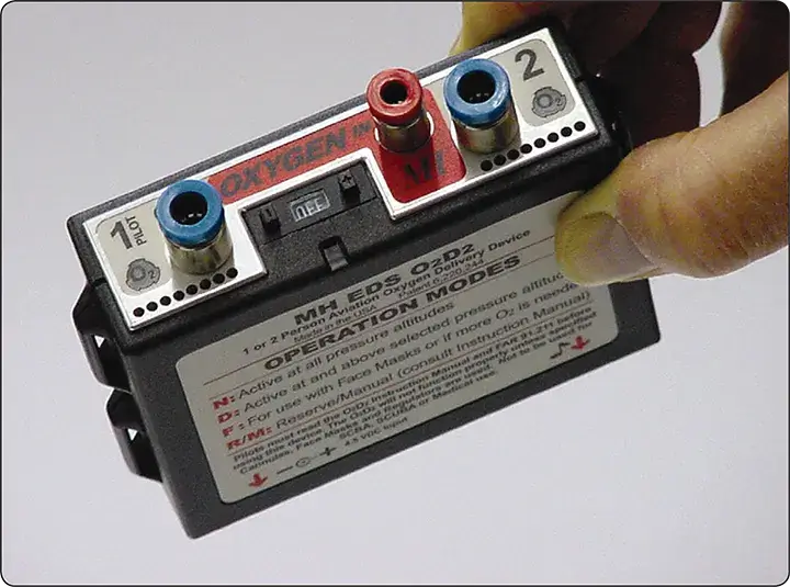
Permanently installed electronic pulse-demand systems are also available. They may integrate an electronic valve or regulator with the oxygen cylinder and include an emergency bypass that provides continuous-flow oxygen if the electronic system malfunctions.
An LCD control panel may display operating parameters and allow adjustments to system settings. Electronic oxygen metering has also been developed for passenger emergency oxygen applications in transport aircraft. [Figure 17]

Oxygen Plumbing and Valves
Tubing and fittings connect the various components of an aircraft oxygen system. Permanent installations commonly use metal tubing, with stainless steel generally used in high-pressure sections and aluminum often used in lower-pressure sections. Flexible hoses may be used to connect the oxygen supply to masks and other components.
The materials and tubing arrangement depend on the system pressure, aircraft design, and applicable requirements.
Oxygen Tubing Identification
Installed oxygen tubing is identified using markings or color-coded tape applied at the ends and at specified intervals along the tubing.
The source material describes a green band marked “BREATHING OXYGEN,” together with a black rectangular symbol on a white background border strip. Identification requirements may vary, so the applicable aircraft maintenance documentation should be consulted. [Figure 18]

Oxygen Tubing Fittings
Tubing-to-tubing fittings in oxygen systems commonly use straight threads to receive flared tube connections. Tubing-to-component fittings may have straight threads on the tubing end and tapered pipe threads on the component end.
Fittings are commonly made from materials compatible with the tubing, such as aluminum or steel. Both flared and flareless fittings may be used, depending on the system design.
Types of Oxygen System Valves
Five types of valves are commonly found in high-pressure gaseous oxygen systems:
- Filler valvesCheck valves
- Shutoff valves
- Pressure-reducing valves
- Pressure-relief valves
These valves perform functions similar to those in other fluid systems, but oxygen system components must be designed and maintained for oxygen service.
Slow-Opening Oxygen Shutoff Valves
Oxygen supports combustion, and materials can ignite more readily in oxygen-enriched environments. A particularly important hazard occurs when high-pressure oxygen is allowed to enter a low-pressure area rapidly.
Rapid pressurization can cause adiabatic compression. The oxygen is compressed quickly, with little time for heat to dissipate. The resulting temperature rise can ignite contaminants or materials within the system.
For example, a particle of oil, grease, or other contamination may ignite when exposed to high-pressure oxygen. Under certain conditions, even metallic components can burn in an oxygen-rich environment.
To reduce this hazard, oxygen shutoff valves are designed to open slowly, limiting the rate at which oxygen enters a low-pressure section.. [Figure 19]

Technicians must also open oxygen valves slowly and follow the applicable servicing procedures. Oxygen equipment must be kept free from oil, grease, fuel, and other contaminants.
Pressure-Relief Valves and Blowout Discs
Oxygen cylinders and high-pressure systems may incorporate pressure-relief valves to protect against excessive pressure. In some installations, the relief valve is connected to an indicating or blowout disc located in a conspicuous position, such as the aircraft fuselage.
The source material notes that many blowout discs are green. If a disc is missing or shows evidence of activation, the cause must be investigated in accordance with the aircraft maintenance instructions before flight. [Figure 20]

Chemical Oxygen Systems
Chemical oxygen systems are primarily used as portable oxygen equipment or as emergency oxygen supplies in pressurized aircraft.
Portable chemical oxygen systems may be similar in application to portable gaseous oxygen cylinders. Integrated chemical oxygen systems are commonly used in transport aircraft as a backup in the event of cabin pressurization failure. [Figure 21]

Passenger Chemical Oxygen Generators
In transport aircraft, chemical oxygen generators are commonly installed in overhead passenger service units (PSUs). Each passenger station is connected to an oxygen mask and hose.
When cabin depressurization occurs, or when the flight crew activates the system, a compartment door opens and the masks deploy. Pulling the mask into the usable position may activate the generator through an electrical mechanism or an ignition hammer, depending on the system design.
The chemical reaction produces oxygen that flows through the hose to the passenger mask. The duration of oxygen production is predetermined by the generator design. The source material identifies a typical duration of approximately 10–20 minutes, intended to provide oxygen while the aircraft descends to an altitude where supplemental oxygen is no longer required.
Advantages and Limitations
Chemical oxygen systems produce oxygen only when activated. This reduces the need to store oxygen as a high-pressure gas and can save space and weight compared with some gaseous oxygen installations.
Each passenger row grouping may have its own independent generator. The oxygen flow is commonly controlled by calibrated orifices in the hose connections.
However, chemical oxygen generators have important limitations. Once activated, they generally cannot be shut off and continue producing oxygen until the chemical reaction is complete. They also generate heat and must be handled in accordance with the manufacturer’s instructions.
Activated or unserviceable chemical oxygen generators must be handled, transported, and replaced according to applicable hazardous-material and maintenance requirements.
Liquid Oxygen (LOX) Systems
Liquid oxygen systems are uncommon in civilian aviation but may be found in former military aircraft that have entered civilian service.
Liquid oxygen must be stored in a specially designed container that maintains the required low temperature. The system also includes plumbing and components that convert the liquid oxygen into a usable gas.
The conversion assembly typically uses a controlled heat exchanger consisting of tubing and valves. Pressure-relief provisions are included to protect the system against excessive pressure caused by temperature changes.
Once the liquid oxygen has vaporized into gaseous oxygen, the downstream delivery system is similar to a comparable gaseous oxygen system. Pressure-demand regulators and masks may be used.
Because LOX systems have unique storage, servicing, and safety requirements, the manufacturer’s maintenance instructions must be consulted whenever such a system is encountered.