
Understanding the theory of flight is essential for anyone involved in aircraft maintenance and repair. An aircraft is made up of many components, including the fuselage, empennage, wings, and flight control surfaces. Helicopters have additional components and operating principles, such as the main rotor, anti-torque rotor, and autorotation.
The study of physics, particularly aerodynamics, explains how these components interact with the surrounding air and how the forces acting on an aircraft allow it to fly. This section introduces the fundamental principles of flight, including the four forces, lift generation, airfoil characteristics, airflow behavior, and aircraft axes of rotation.
Four Forces of Flight
During flight, there are four forces acting on an airplane. These forces are lift, weight, thrust, and drag. [Figure 1]
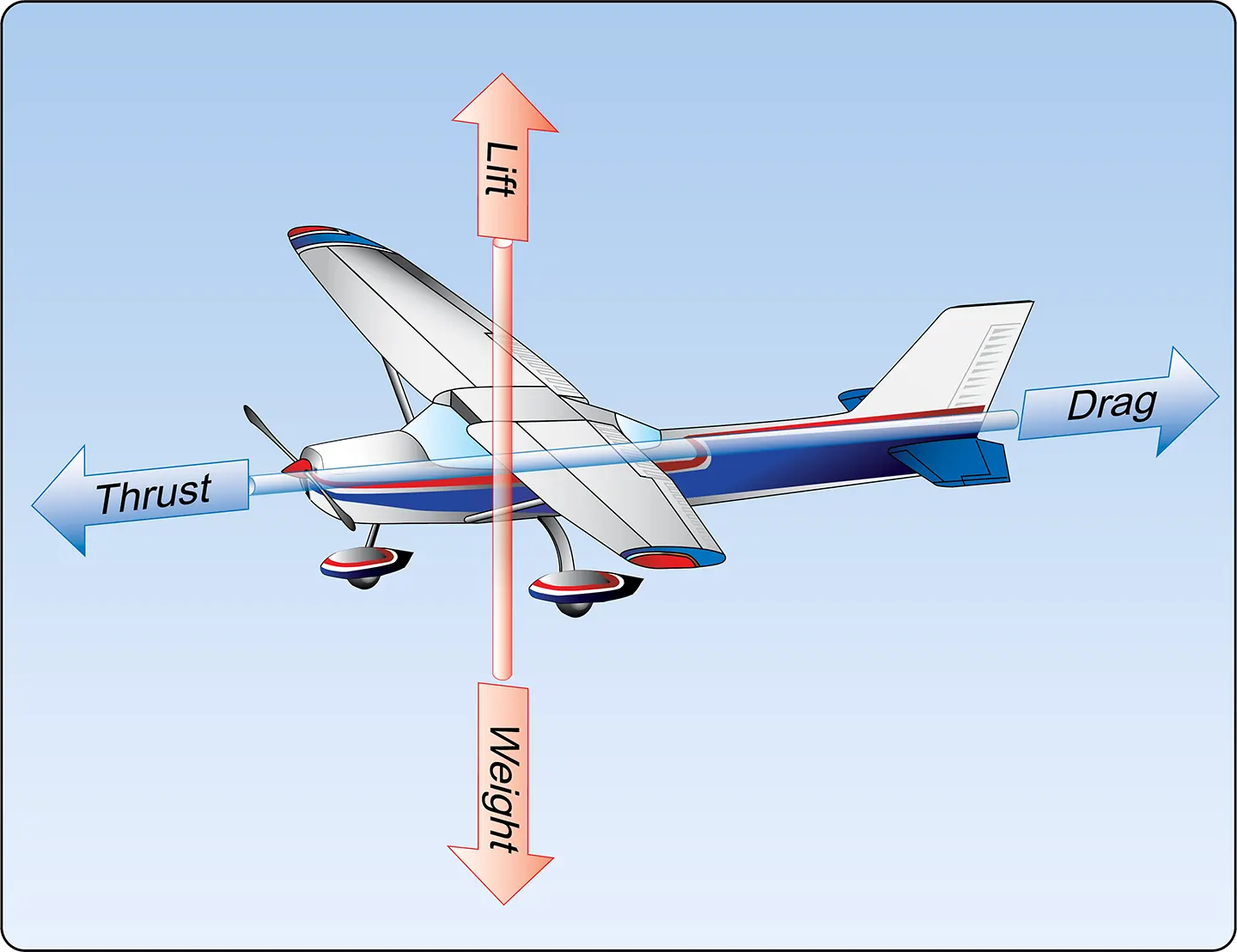
Lift is the upward aerodynamic force created by the wing, weight is the force of gravity acting on the airplane’s mass, thrust is the force created by the airplane’s propeller or turbine engine, and drag is the aerodynamic resistance opposing the airplane’s motion through the air.
All four forces are measured in pounds in the customary system of units. Whenever these forces are not balanced, the airplane’s motion or flight condition changes. The possibilities are as follows:
- When an airplane accelerates forward, thrust is greater than drag.
- When an airplane decelerates, drag is greater than thrust.
- When an airplane maintains a constant forward velocity in straight-and-level flight, thrust and drag are equal.
- When an airplane climbs at a constant speed and flightpath angle, the lift and weight relationship depends on the direction of the flightpath. Lift is not necessarily greater than weight.
- When an airplane descends at a constant speed and flightpath angle, lift is not necessarily less than weight.
- When an airplane maintains a constant altitude in straight-and-level, unaccelerated flight, lift and weight are equal.
The four forces act in different directions. Lift and weight act approximately perpendicular and parallel to the Earth’s surface, respectively, during straight-and-level flight. Thrust acts in the direction of the airplane’s propulsion, while drag acts opposite the airplane’s motion through the air.
The balance of these forces determines whether the airplane accelerates, decelerates, climbs, descends, or maintains steady flight.
Bernoulli’s Principle and Subsonic Flow
The basic concept of subsonic airflow and the resulting pressure differences is associated with the work of Daniel Bernoulli, a Swiss physicist.
Bernoulli’s principle, as it is commonly applied to aerodynamics, states that as the velocity of a fluid increases, its static pressure decreases, provided there is no energy added to or taken away from the fluid and the other conditions required for the relationship are satisfied.
A direct application of Bernoulli’s principle is the study of air as it flows through either a converging or a diverging passage and the relationship of these findings to aviation.
A converging duct is one whose cross-sectional area becomes progressively smaller from the entry to the exit. A diverging duct is the opposite, with the cross-sectional area becoming larger from the entry to the exit.
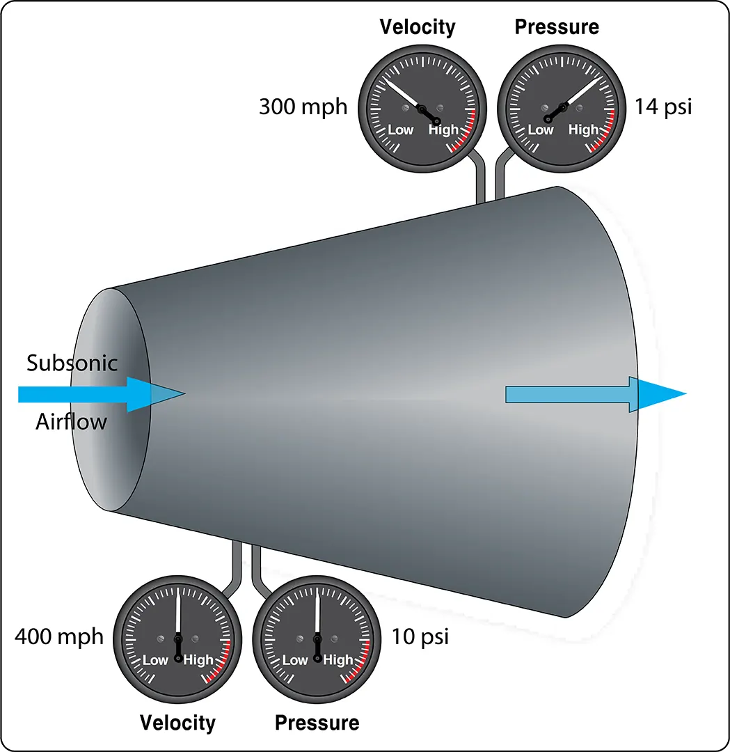
Figure 2 shows a converging-shaped duct, with air entering on the left at subsonic velocity and exiting on the right.

Notice that the air exits at an increased velocity and decreased static pressure when looking at the pressure and velocity gauges and their indicated values.
For steady airflow through a duct, the mass flow rate must remain constant. As the cross-sectional area decreases, the air must increase its velocity to maintain the same mass flow rate, assuming the flow conditions remain suitable for this relationship.
In a diverging duct, the opposite occurs under subsonic flow conditions. From the entry point to the exit point, the duct spreads out and its cross-sectional area becomes larger. [Figure 3]
With the increase in cross-sectional area, the velocity of the air decreases and its static pressure increases. The total energy of the airflow remains constant under the ideal conditions described by Bernoulli’s principle. What is lost in kinetic energy as the velocity decreases is gained in static pressure.
In the discussion of Bernoulli’s principle in the Fluid Mechanics section, a venturi was shown in Figure 4.
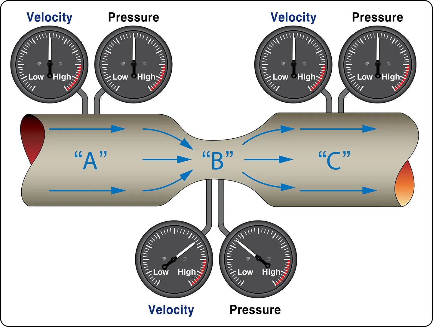
In Figure 5, a venturi is shown again, only this time a wing is shown positioned in the recess where the venturi’s converging shape is located.
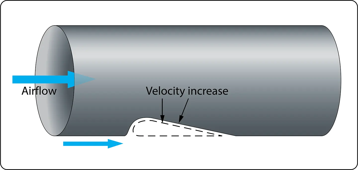
There are two arrows showing airflow. The large arrow shows airflow within the venturi, and the small arrow shows the airflow outside the venturi as it approaches the leading edge of the wing.
In the converging part of the venturi, velocity increases and static pressure decreases. A similar relationship occurs in the airflow around a wing. The airflow over the upper surface of the wing accelerates, and the static pressure generally decreases.
The air reaching the leading edge of the wing divides into two streams. Some of the air flows over the top of the wing, while some flows along the bottom.
The curvature and shape of the wing influence the airflow around it. The airflow over the upper surface generally accelerates, producing a lower static pressure than the pressure on the lower surface. This pressure difference contributes to the lift generated by the wing.
Important: The explanation of lift is not based on the idea that air passing over the top of the wing must travel farther and therefore move faster in order to meet the air that travels underneath at the trailing edge. There is no requirement for the two air streams to meet at the same time. The actual airflow pattern is determined by the wing’s shape, angle of attack, and surrounding flow conditions.
For the wing shown in Figure 5, imagine it is 5 ft wide and 15 ft long, giving a surface area of 75 ft² (10,800 in²).
If the difference in static pressure between the top and bottom is 0.1 psi, there will be 0.1 lb of lift for each square inch of surface area. Since there are 10,800 in² of surface area, the total lift would be:
0.1 × 10,800 = 1,080 lb
This simplified calculation assumes that the pressure difference is uniform over the entire wing surface.
Lift and Newton’s Third Law
Newton’s third law states that for every action, there is an equal and opposite reaction. In addition to Bernoulli’s principle, Newton’s third law can also be used to explain the lift created by a wing.
As air travels around a wing and leaves the trailing edge, the wing produces a downward deflection of the airflow, known as downwash. Since a force is required to change the direction of the airflow, there must be an equal and opposite reaction force acting on the wing. This reaction contributes to the lift produced by the wing.
To calculate lift based on Newton’s laws, Newton’s second law and the formula below can be used:
Force = Mass × Acceleration
The mass would be the mass of air affected by the wing during a given time interval, and the acceleration would be the change in velocity imparted to that air.
The lift on a wing as described by Bernoulli’s principle and the lift described by Newton’s third law are not separate or independent forces. They are two different ways of explaining the same aerodynamic process: the generation of lift by the wing.
Airfoils
An airfoil is a shape designed to produce an aerodynamic force when air flows over its surface. The force may act primarily as lift or may be used to produce thrust, depending on the purpose and orientation of the airfoil.
An airfoil can be the wing of an airplane, the blade of a propeller, the rotor blade of a helicopter, or the fan blade of a turbofan engine.
The wing of an airplane moves through the air because the airplane is in motion and generates lift through the aerodynamic principles previously described.
By comparison, a propeller blade, helicopter rotor blade, or turbofan engine fan blade rotates through the air. These rotating blades can be viewed as rotating wings, as is common with helicopters when they are called rotary-wing aircraft.
A rotating airfoil can produce lift or thrust depending on its design and operating conditions.
In Figure 6, an airfoil, or wing, is shown with some of the terminology used to describe a wing.
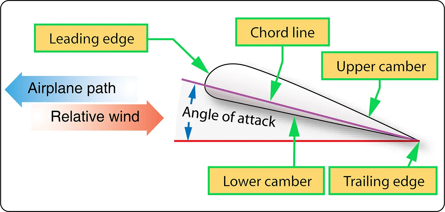
The terms and their meanings are as follows:
Camber
The camber of a wing refers to the curvature of its upper and lower surfaces. The upper surface generally has more pronounced curvature, unless the wing is a symmetrical airfoil, which has the same curvature on both sides.
The bottom of the wing is often relatively flat. The shape of the airfoil influences the velocity and pressure distribution around the wing. Together with the angle of attack, this pressure distribution contributes to the lift generated by the wing.
Chord Line
The chord line is an imaginary straight line running from the wing’s leading edge to its trailing edge.
The angle between the chord line and the longitudinal reference axis of the airplane is known as the angle of incidence.
Relative Wind
The relative wind is the direction of airflow relative to the aircraft or wing. In normal flight circumstances, the relative wind is opposite the direction of the aircraft’s flightpath.
- If the flightpath is forward, the relative wind is backward.
- If the flightpath is forward and upward, the relative wind is backward and downward.
- If the flightpath is forward and downward, the relative wind is backward and upward.
Therefore, the relative wind is parallel to the flightpath but travels in the opposite direction.
Angle of Attack
The angle between the chord line and the relative wind is known as the angle of attack.
As the angle of attack increases, lift generally increases up to a certain point. If the angle of attack becomes too great, the airflow can separate from the wing’s upper surface, resulting in a significant loss of lift.
When this occurs, a condition known as a stall takes place. A stall is caused by exceeding the critical angle of attack, not simply by flying at a low airspeed.
Wing Planforms
There are a number of different shapes, known as wing planforms, that a wing can have.
A rectangular wing is very common on small general aviation airplanes. An elliptical or tapered wing can also be used. Each design has different aerodynamic characteristics, including differences in lift distribution and stall behavior.
For airplanes that operate at high subsonic speeds, sweptback wings are common. For supersonic flight, a delta-shaped wing may be used.
Aspect Ratio
The aspect ratio of a wing is the relationship between its wingspan and its average chord. More precisely, it is calculated by dividing the square of the wingspan by the wing area.
Aspect Ratio = Wingspan² ÷ Wing Area
A wing with a long span and a relatively narrow chord is said to have a high aspect ratio.
A higher aspect ratio generally produces less induced drag for a given lift and flight condition. High-aspect-ratio wings are typically found on gliders and sailplanes because they are designed for efficient flight.
Angle of Incidence and Washout
The angle of incidence of a wing is the angle formed between the wing chord line and the aircraft’s longitudinal reference axis.
Many airplanes are designed with a greater angle of incidence at the root of the wing than at the tip. This difference is known as washout, which is a form of geometric wing twist.
Washout causes the inboard portion of the wing to operate at a higher effective angle of attack than the outboard portion. As the aircraft approaches a stall, the root generally stalls before the tip. This helps maintain aileron effectiveness during the initial stages of a wing stall.
Boundary Layer Airflow
The boundary layer is a relatively thin layer of air flowing over the surface of the wing and, for that matter, all other surfaces of the airplane.
Because air has viscosity, the airflow immediately next to the surface is slowed by friction. The velocity of the airflow increases with distance from the surface until it approaches the velocity of the surrounding free stream.
As the wing moves through the air, the boundary layer initially may flow smoothly over the streamlined shape of the airfoil. This type of flow is called a laminar boundary layer.
As the boundary layer develops along the wing, it may transition from laminar flow to turbulent flow. The point at which this change occurs is called the transition point.
A turbulent boundary layer contains more mixing and generally has greater skin-friction drag than a laminar boundary layer. However, a turbulent boundary layer also has more energy near the surface and can sometimes resist flow separation better than a laminar boundary layer.
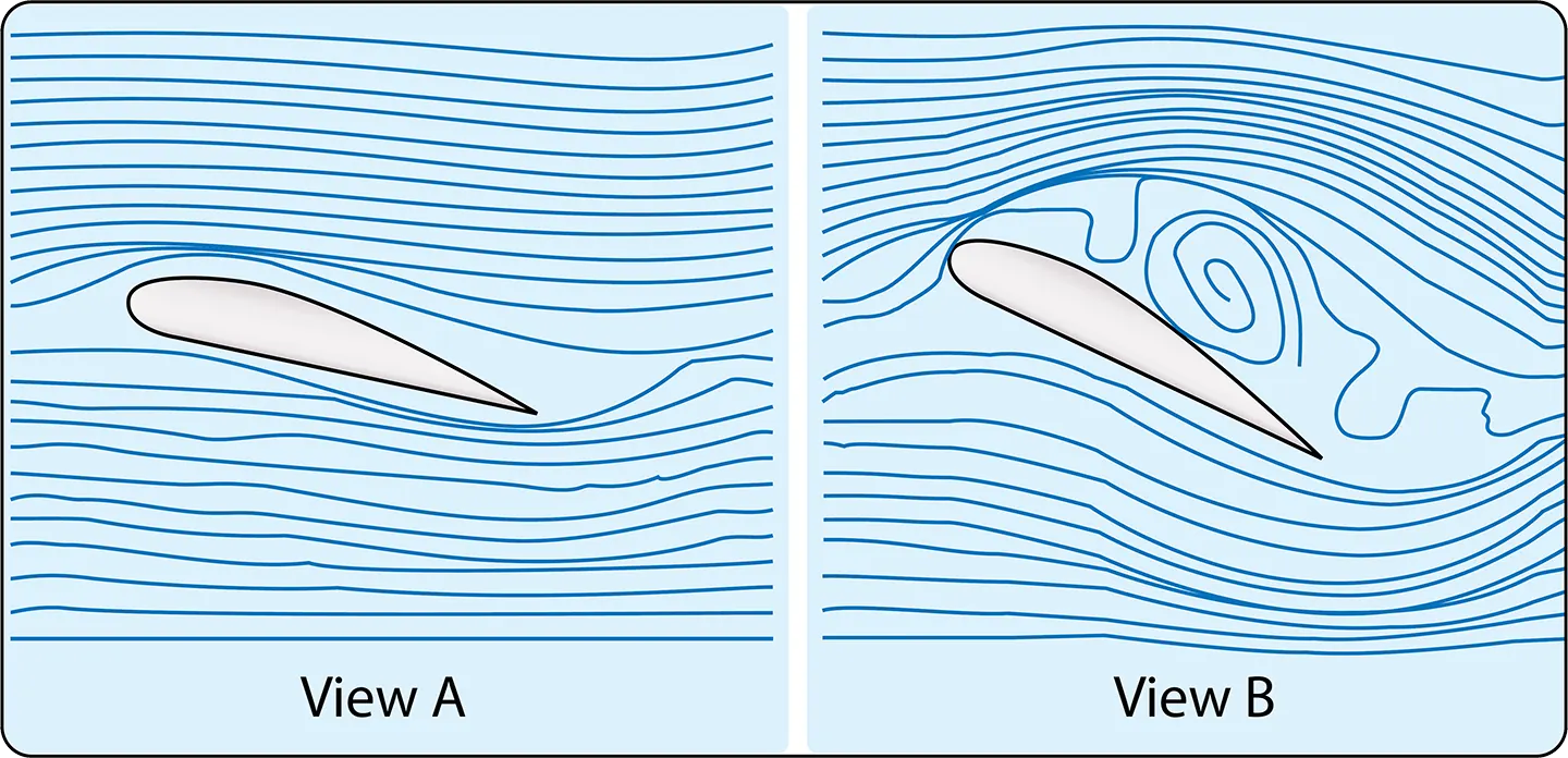
As the angle of attack increases, the pressure distribution over the wing changes. An adverse pressure gradient can cause the boundary layer to slow down and eventually separate from the wing’s surface.
When airflow separation becomes extensive, the wing experiences a substantial loss of lift and an increase in drag. This condition is associated with a stall.
In Figure 7, view A shows a normal angle of attack with airflow remaining attached to the wing. View B shows an extreme angle of attack, with airflow separating and becoming highly disturbed over the upper surface. In view B, the wing is in a stall.
Boundary Layer Control
One way of managing boundary-layer airflow and reducing its negative effects is to make the wing’s surface as smooth as possible and keep it free of dirt, ice, and debris.
Surface contamination can alter the airflow over the wing, increase drag, and reduce the maximum lift that can be produced. Ice forming on a wing can be particularly serious because it changes the airfoil shape and can disrupt the boundary layer.
On a high-speed airplane, even small amounts of contamination, such as insects on the wing’s leading edge, can negatively affect airflow.
Other methods of controlling boundary-layer airflow include wing leading-edge slots, suction through small holes on the wing’s upper surface, and devices called vortex generators.
Wing Leading-Edge Slots
A wing leading-edge slot is a passage that allows air to flow from the lower side of the wing through a duct to the upper surface.
As the air flows through the slot, it is directed along the upper surface at a relatively high velocity. This helps energize the boundary layer and delay airflow separation from the wing.
Boundary-Layer Suction
Another method of controlling boundary-layer airflow is to create suction on the upper surface of the wing through a large number of small holes.
The suction removes some of the slow-moving air near the surface, helping the remaining airflow stay attached to the wing. This method is known as boundary-layer suction.
Vortex Generators
Vortex generators are small aerodynamic devices installed on the upper surface of a wing. They are commonly used on aircraft operating at high subsonic speeds.
They are positioned to produce small vortices that mix higher-energy air from outside the boundary layer with the slower-moving air near the wing surface. This helps energize the boundary layer and delay airflow separation.
On some high-speed aircraft, shock waves can form on the wing when local airflow reaches supersonic speed. These shock waves can contribute to boundary-layer separation. Vortex generators can help reduce the tendency for separation by improving the energy of the boundary layer.
Wingtip Vortices
Wingtip vortices are caused by the pressure difference between the lower and upper surfaces of a wing.
The pressure below the wing is generally higher than the pressure above it. Air tends to move from the higher-pressure region below the wing around the wingtip toward the lower-pressure region above the wing.
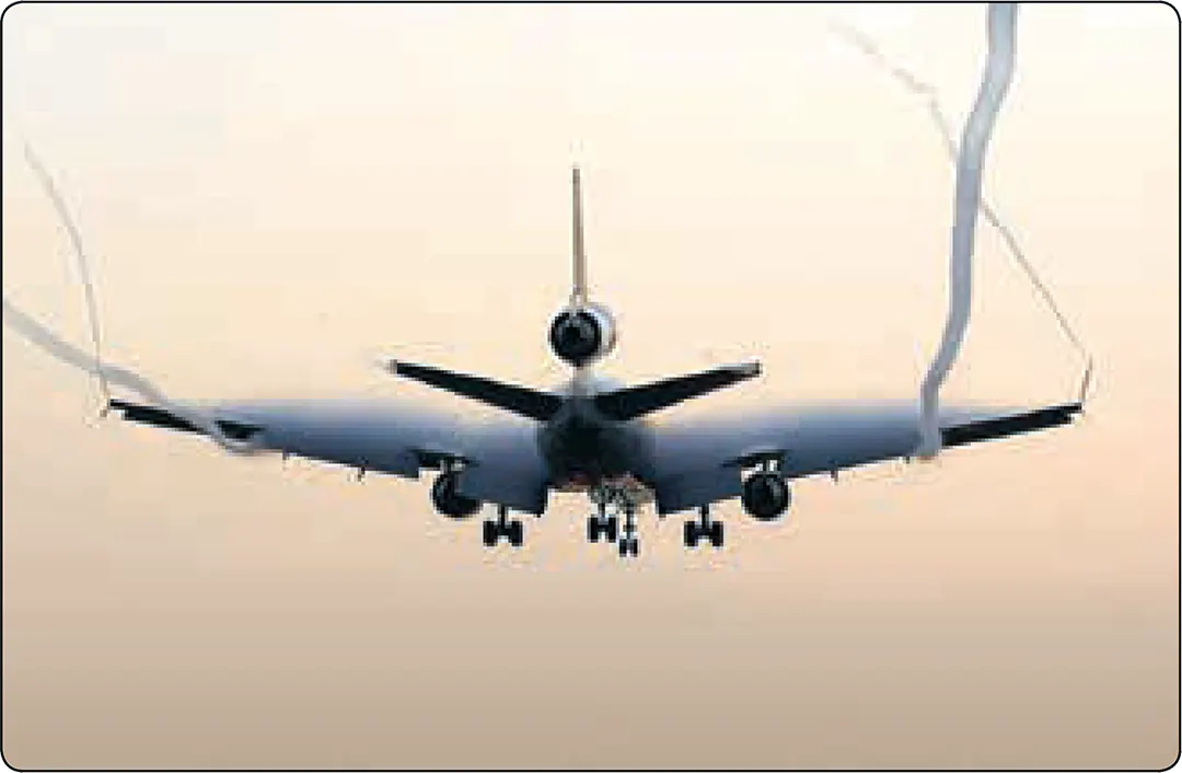
This movement produces a rotating airflow pattern, or vortex, that trails behind each wingtip whenever the wing is producing lift.
Wingtip vortices are a major source of wake turbulence. They are an important factor in determining how closely one airplane can follow another during approach and landing.
The wake turbulence produced by a large airplane can cause a smaller airplane following too closely to experience severe rolling moments or loss of control.
Vortices from the wing and horizontal stabilizer are visible on the MD-11 shown in Figure 8.
Upwash and Downwash
Upwash and downwash refer to the effect an airfoil has on the surrounding airflow.
Upwash is the upward deflection of the oncoming airstream as it approaches the wing.
Downwash is the downward deflection of the airflow after it has passed over the wing and leaves the trailing edge.
This downward deflection of the airflow is associated with the action and reaction described under lift and Newton’s third law.
Axes of an Aircraft
An airplane in flight is controlled around one or more of three axes of rotation. These axes are the longitudinal, lateral, and vertical axes.
On the airplane, all three axes intersect at the center of gravity (CG). As the airplane rotates around one of these axes, it rotates about an axis passing through or near the center of gravity.
The center of gravity is sometimes referred to as the center of rotation in introductory descriptions of aircraft motion.
On the brightly colored airplane shown in Figure 9, the three axes are shown in different colors:
- Red: Vertical axis
- Blue: Longitudinal axis
- Orange: Lateral axis
The flight control that makes the airplane move around each axis is shown in a matching color.
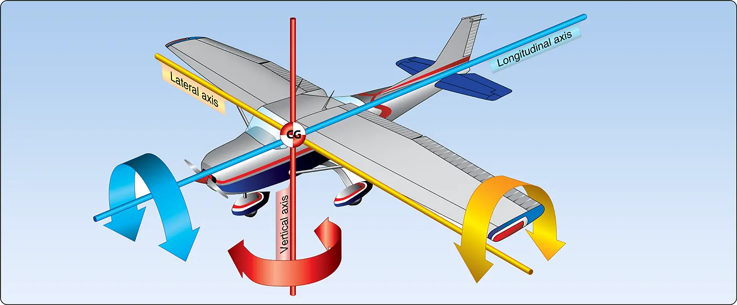
The rudder, shown in red, causes the airplane to move around the vertical axis. This movement is described as yaw.
The elevator, shown in orange, causes the airplane to move around the lateral axis. This movement is described as pitch.
The ailerons, shown in blue, cause the airplane to move around the longitudinal axis. This movement is described as roll.