
Fluid mechanics is the study of liquids and gases and the forces that act on them. It is an important part of aviation because many aircraft systems depend on the behavior of fluids. The principles of fluid mechanics help explain buoyancy, hydraulic power, fluid pressure, airflow, and the generation of lift by an aircraft wing.
Table of Contents
Table of Contents
What Is a Fluid?
By definition, a fluid is any substance that is able to flow if it is not in some way confined or restricted. Liquids and gases are both classified as fluids, and they often act in a very similar way.
One significant difference comes into play when a force is applied to these fluids. Liquids tend to be incompressible, while gases are highly compressible.
Many of the principles on which aviation is based, such as the theory of lift on a wing and the force generated by a hydraulic system, can be explained and quantified by using the laws of fluid mechanics.
Buoyancy
A solid body submerged in a liquid or a gas weighs less than when weighed in free space. This is because of the upward force, called buoyant force, which any fluid exerts on a body submerged in it.
An object will float when the buoyant force can support its weight. Objects denser than the fluid tend to sink, but they still appear to lose part of their weight when submerged. A person can lift a larger weight under water than they can possibly lift in the air.
The following experiment is illustrated in Figure 1.

The overflow can is filled to the spout with water. The heavy metal cube is first weighed in still air and weighs 10 lb. It is then weighed while completely submerged in the water, and it weighs 3 lb.
The difference between the two weights is the buoyant force of the water. As the cube is lowered into the overflow can, the water is caught in the catch bucket. The volume of water that overflows equals the volume of the cube. The volume of irregularly shaped objects can also be measured by using this method.
If this experiment is performed carefully, the weight of the water displaced by the metal cube exactly equals the buoyant force of the water, which the scale shows to be 7 lb.
Archimedes (287–212 B.C.) performed similar experiments. As a result, he discovered that the buoyant force which a fluid exerts upon a submerged body is equal to the weight of the fluid the body displaces. This statement is referred to as Archimedes’ principle.
This principle applies to all fluids, gases as well as liquids. Just as water exerts a buoyant force on submerged objects, air exerts a buoyant force on objects surrounded by it.
The amount of buoyant force available to an object can be calculated by using the following formula:
Buoyant Force = Volume of Fluid Displaced × Weight Density of Fluid
For a completely submerged object, the volume of fluid displaced is equal to the volume of the object.
If the buoyant force available when an object is submerged is less than the object’s weight, the object will sink. Its apparent weight while submerged will be reduced by the buoyant force. If the buoyant force can support the object’s weight, the object will float. When floating in equilibrium, the buoyant force equals the object’s weight.
Example: A 10-ft³ object weighing 700 lb is placed in pure water. Will the object float? If the object sinks, what is its measurable weight in the submerged condition? If the object floats, how many cubic feet of its volume are below the waterline?
Buoyant Force = Volume of Object × Weight Density of Fluid
= 10 × 62.4
= 624 lb
The object will sink because the buoyant force is less than the object’s weight. The difference between the object’s weight and the buoyant force will be its measurable weight:
700 − 624 = 76 lb
Two good examples of buoyancy are a helium-filled airship and a seaplane on floats. An airship is able to float in the atmosphere, and a seaplane is able to float on water. Both depend on buoyancy to support their weight.
Figure 2 shows a De Havilland Twin Otter seaplane with a gross takeoff weight of 12,500 lb. At a minimum, the floats on this airplane must displace a weight of water equal to the airplane’s weight.

According to the regulatory requirement cited in the original material, the floats must provide 80 percent more buoyancy than the minimum needed to support the airplane. For this airplane, the necessary size of the floats would be calculated as follows:
Step 1: Divide the airplane weight by the weight density of water.
12,500 ÷ 62.4 = 200.3 ft³
Step 2: Calculate 80 percent of this volume.
200.3 × 80% = 160.2 ft³
Step 3: Add the two volumes together to get the total volume of the floats.
200.3 + 160.2 = 360.5 ft³
By looking at the Twin Otter in Figure 2, it is obvious that much of the volume of the floats is out of the water. This is accomplished by making sure the floats have at least 80 percent more volume than the minimum necessary.
Some of the large Goodyear airships have a volume of 230,000 ft³. Since the fluid they are surrounded by is air, to find the buoyant force of the airship, the volume of the airship is multiplied by the weight density of air (0.07651 lb/ft³).
For this Goodyear airship, the buoyant force is:
230,000 × 0.07651 = 17,597 lb
Figure 3 shows an inside view of the Goodyear airship.
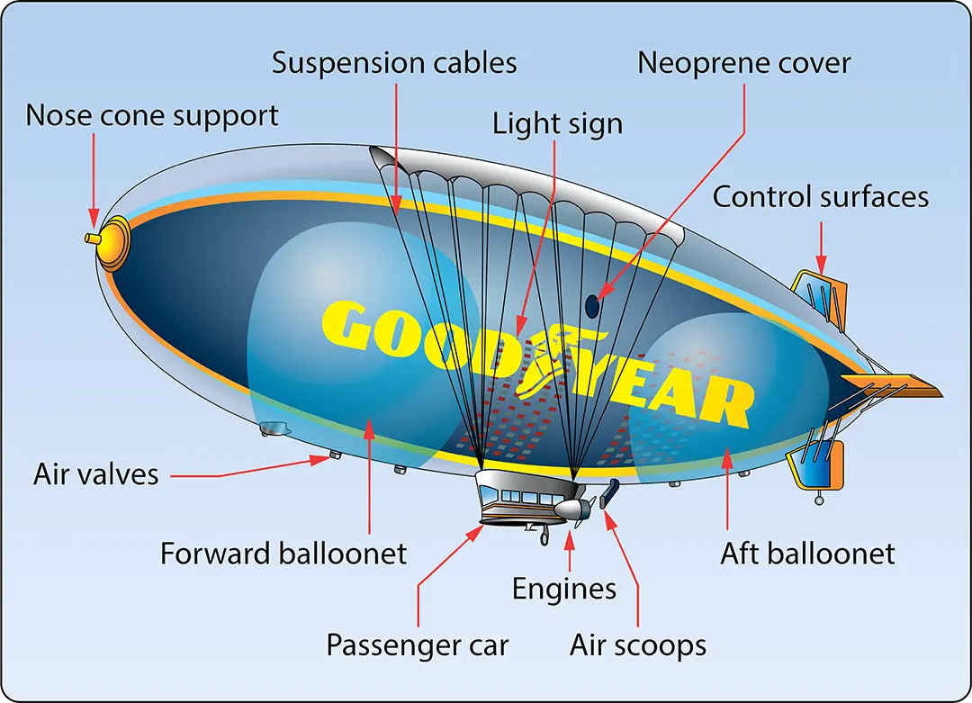
The forward and aft ballonets are air chambers within the airship. Through the air scoop, air can be pumped into the ballonets or evacuated from them in order to control the weight of the airship. Controlling the weight of the airship controls how much positive or negative lift it has.
Although the airship is classified as a lighter-than-air aircraft, it is in fact flown in a condition slightly heavier than air.
Fluid Pressure
The pressure exerted on the bottom of a container by a liquid is determined by the height of the liquid and not by the shape of the container. This can be seen in Figure 4, where three different shapes and sizes of containers are full of colored water.
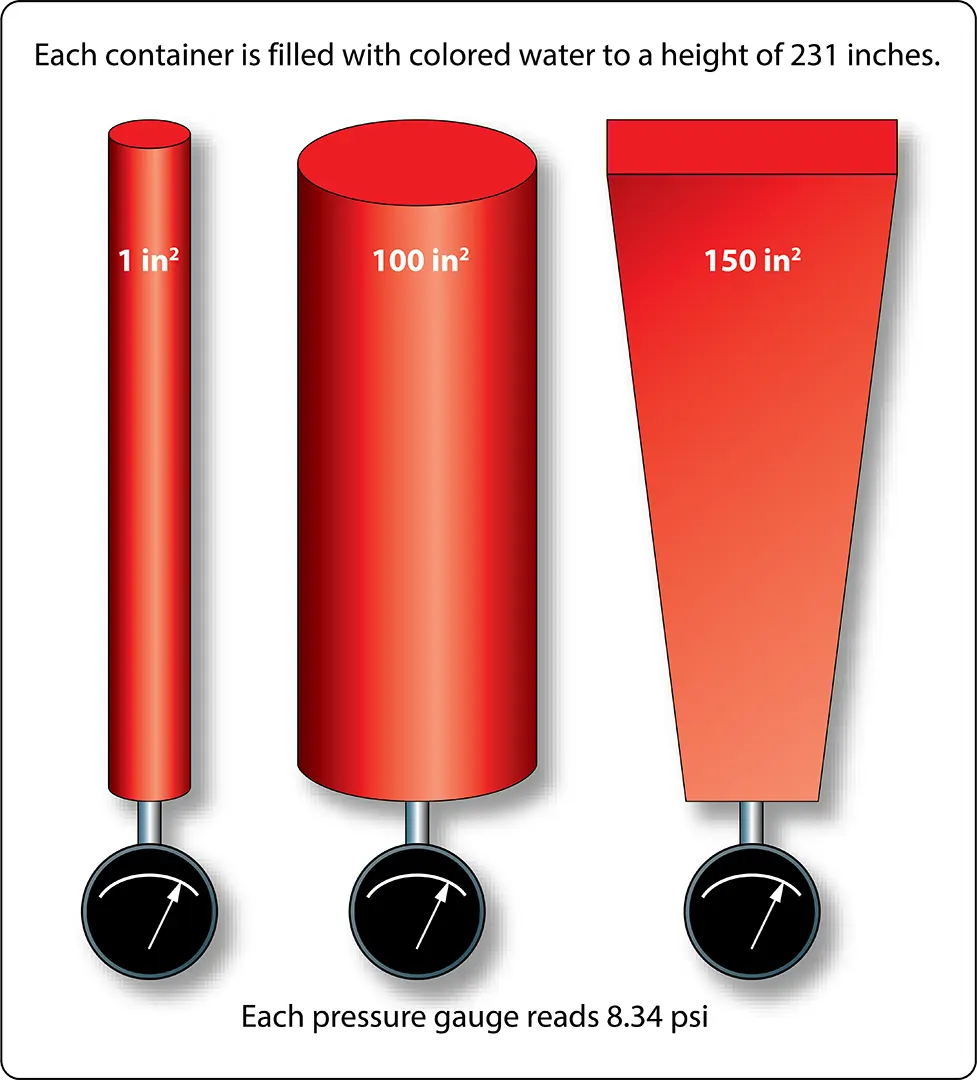
Even though they are different shapes and have different volumes of liquid, each one has a height of 231 inches. Each one would exert a pressure on the bottom of 8.34 psi because of this height.
The container on the left, with a surface area of 1 in², contains a volume of 231 in³ (one gallon). One gallon of water weighs 8.34 lb, which is why the pressure on the bottom is 8.34 psi.
Still thinking about Figure 4, if the pressure were measured halfway down, it would be half of 8.34, or 4.17 psi. In other words, the pressure can be changed by varying the height of the column.
Pressure based on the column height of a fluid is known as static pressure. With liquids, such as gasoline, it is sometimes referred to as a head of pressure.
For example, if a carburetor needs to have 2 psi supplied to its inlet, or head of pressure, this could be accomplished by having the fuel tank positioned the appropriate number of inches higher than the carburetor.
As identified in the previous paragraph, pressure due to the height of a fluid column is known as static pressure. When a fluid is in motion, its motion is associated with dynamic pressure, also commonly referred to as ram pressure in aviation.
When dynamic pressure and static pressure are added together, the result is known as total pressure under the usual conditions for this basic relationship.
In the inlet of a gas turbine engine, for example, total pressure is often measured to provide a signal to the fuel metering device or to provide a signal to a gauge on the flight deck.
Pascal’s Law
The foundations of modern hydraulics and pneumatics were established in 1653 when Pascal discovered that pressure applied to an enclosed fluid acts equally and undiminished in all directions. This pressure acts at right angles to containing surfaces.
When the pressure in a fluid is caused solely by the fluid’s height, the pressure against the walls of the container is equal at any given level. However, it is not equal if the pressure at the bottom is compared with the pressure halfway down.
The concept of pressure set up in an enclosed fluid, and how it relates to the force acting on the fluid and the surface area through which it acts, is described by Pascal’s law.
In Figure 4, if a piston is placed at the top of the cylinder and an external force pushes down on the piston, additional pressure will be created in the liquid.
If the additional pressure is 100 psi, this 100 psi will act equally and undiminished throughout the enclosed liquid. The gauge at the bottom will now read 108.34 psi. If a gauge were positioned halfway down the cylinder, it would read 104.17 psi, which is found by adding 100 to half of 8.34.
Pascal’s law, when dealing with the variables of force, pressure, and area, is expressed by the following formula:
Force = Pressure × Area
In this formula, force is measured in pounds, pressure in pounds per square inch (psi), and area in square inches.
By rearranging the original formula, we have two additional formulas:
Pressure = Force ÷ Area
and
Area = Force ÷ Pressure
An easy and convenient way to remember the formulas for Pascal’s law and the relationship between the variables is with the triangle shown in Figure 5. If the variable we want to solve for is covered up, the position of the remaining two variables shows the proper mathematical relationship.
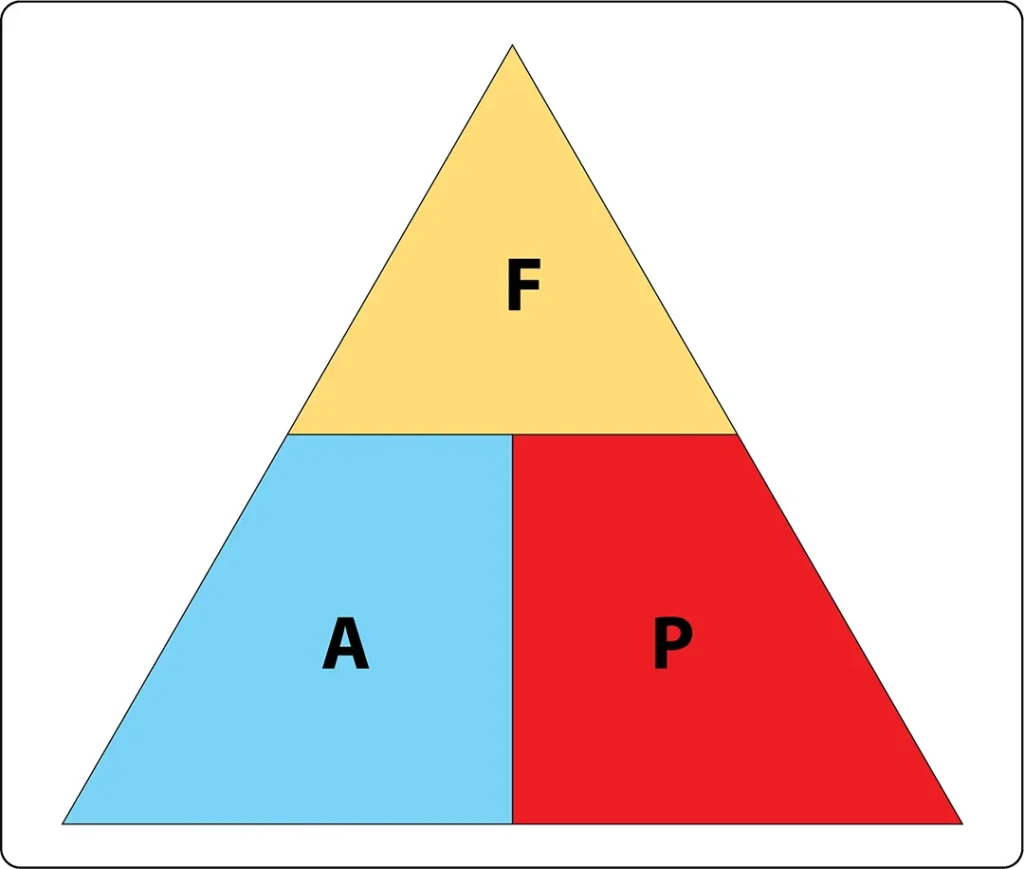
For example, if the “A,” or area, is covered up, what remains is the “F” on the top and the “P” on the bottom, meaning force divided by pressure.
The simple hydraulic system in Figure 6 has 5 lb of force acting on a piston with a 1/2-in² surface area. Based on Pascal’s law, the pressure in the system would be equal to the force applied divided by the area of the piston, or 10 psi.

As shown in Figure 6, the pressure of 10 psi is present throughout the fluid.
The hydraulic system in Figure 7 is a little more complex than the one in Figure 6.

In Figure 7, the input force of 5 lb is acting on a 1/2-in² piston, creating a pressure of 10 psi. The input cylinder and piston are connected to a second cylinder, which contains a 5-in² piston.
The pressure of 10 psi created by the input piston pushes on the piston in the second cylinder, creating an output force of 50 lb.
Often, the purpose of a hydraulic system is to generate a large output force, with the input force being much less. In Figure 7, the input force is 5 lb and the output force is 50 lb, or 10 times greater.
The relationship between the output force and the input force is known as mechanical advantage. The mechanical advantage in Figure 7 would be 50 divided by 5, or 10.
The following formula can be used to calculate mechanical advantage:
Mechanical Advantage = Force Out ÷ Force In
In an ideal hydraulic system, the corresponding distance relationship is:
Distance In ÷ Distance Out = Mechanical Advantage
Earlier in this section when simple machines, such as levers and gears were discussed, it was identified that no machine allows us to gain work. The same statement holds true for a hydraulic system, that we get no more work out of a hydraulic system than we put in.
Since work is equal to force multiplied by distance, if we gain force with a hydraulic system, we must lose distance. We only get the same work out if the system is 100 percent efficient. In a real system, friction and other losses mean that the output work is less than the input work.
In order to determine how far the output piston will move in response to the movement of the input piston, the volume of fluid displaced must be considered.
In the study of geometry, one learns that the volume of a cylinder is equal to the cylinder’s cross-sectional area multiplied by its height. So, when a piston with an area of 2 in² moves down in a cylinder a distance of 10 in, it displaces a volume of fluid equal to 20 in³:
2 in² × 10 in = 20 in³
The 20 in³ displaced by the first piston is what moves through the system and causes the second cylinder’s piston to move.
In a simple two-piston hydraulic system, the relationship between the piston areas and the distances moved is shown by the following formula:
Input Piston Area × Input Distance Moved = Output Piston Area × Output Distance Moved
This formula shows that, in an ideal system, the volume of fluid displaced by the input piston equals the volume that moves the output piston.
This concept is shown in Figure 8, where a small input piston moves a distance of 20 inches, and the larger output piston moves only 1 inch.
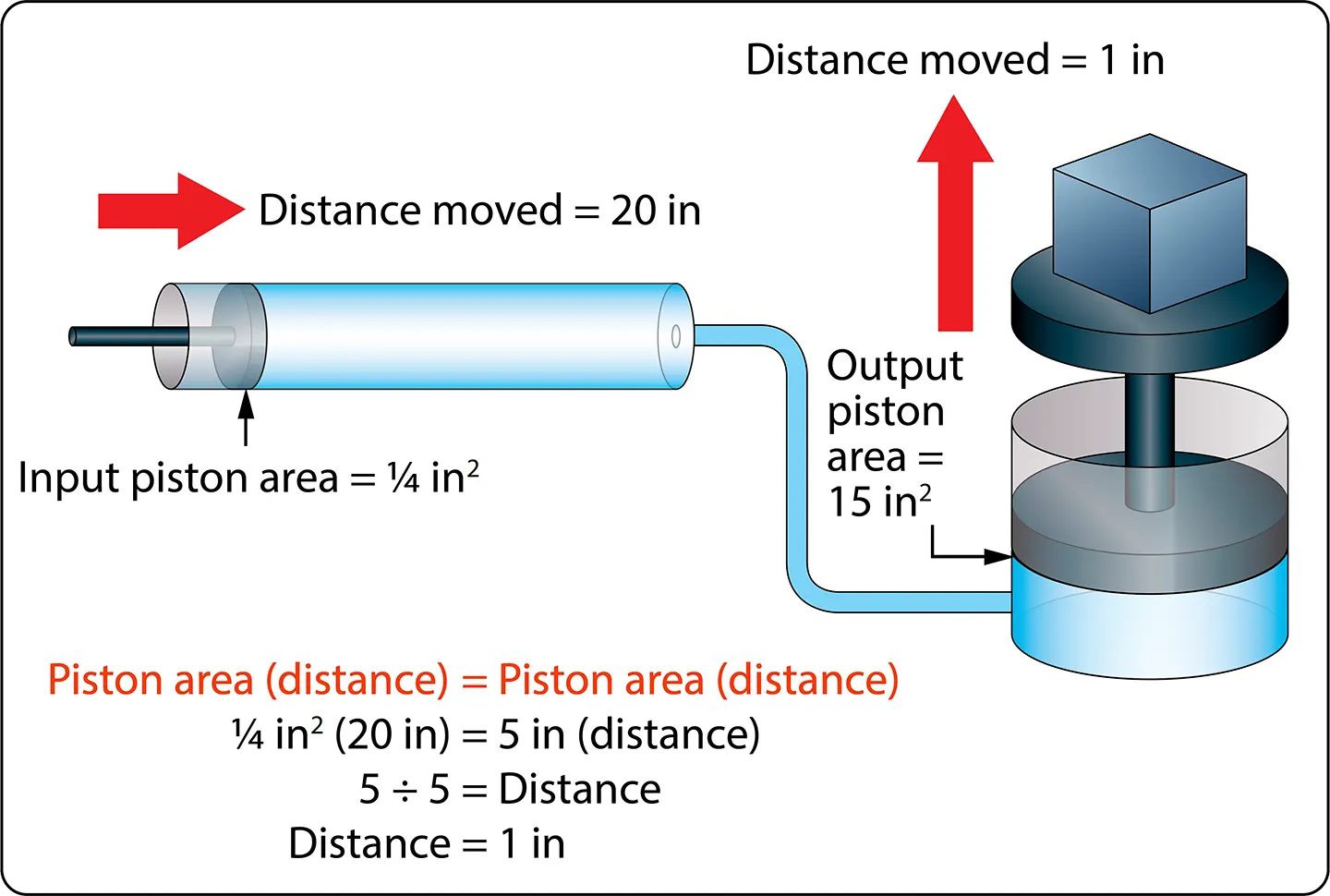
Example: A two-piston hydraulic system, like that shown in Figure 8, has an input piston with an area of 1/4 in² and an output piston with an area of 15 in². An input force of 50 lb is applied, and the input piston moves 30 inches.
What is the pressure in the system, how much force is generated by the output piston, how far would the output piston move, and what is the mechanical advantage?
Step 1: Calculate pressure.
Pressure = Force ÷ Area
= 50 ÷ 1/4
= 200 psi
Step 2: Calculate output force.
Force = Pressure × Area
= 200 × 15
= 3,000 lb
Step 3: Calculate mechanical advantage.
Mechanical Advantage = Force Out ÷ Force In
= 3,000 ÷ 50
= 60
Step 4: Calculate the output piston distance.
Input Piston Area × Input Distance = Output Piston Area × Output Distance
1/4 × 30 = 15 × Output Distance
1/4 × 30 ÷ 15 = Output Distance
Output Distance = 1/2 in
Part of understanding Pascal’s law and hydraulics involves utilizing formulas and recognizing the relationship between the individual variables. Before the numbers are plugged into the formulas, it is often possible to analyze the variables in the system and come to a realization about what is happening.
For example, look at the variables in Figure 8 and notice that the output piston is 60 times larger than the input piston in the numerical example: 15 in² compared to 1/4 in².
That comparison tells us that the output force will be 60 times greater than the input force, and also that the output piston will only move 1/60 as far. Without doing any formula-based calculations, we can conclude that the hydraulic system in this example has a mechanical advantage of 60.
Bernoulli’s Principle
Bernoulli’s principle was originally stated to explain the action of a liquid flowing through tubes with varying cross-sectional areas.
In Figure 9, a tube is shown in which the cross-sectional area gradually decreases to a minimum diameter in its center section. A tube constructed in this manner is called a venturi, or venturi tube.
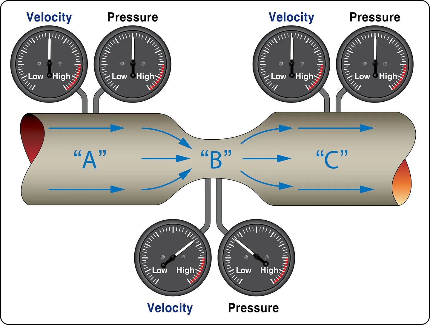
Where the cross-sectional area is decreasing, the passageway is referred to as a converging duct. As the passageway starts to spread out, it is referred to as a diverging duct.
As a liquid, or fluid, flows through the venturi tube, the gauges at points A, B, and C are positioned to register the velocity and static pressure of the fluid.
The venturi in Figure 9 can be used to illustrate Bernoulli’s principle, which states that the static pressure of a fluid, liquid or gas, decreases at points where the velocity of the fluid increases, provided no energy is added to or taken away from the fluid and other conditions, such as elevation, remain unchanged.
The velocity of the fluid is associated with kinetic energy, while its static pressure represents pressure energy.
In the wide sections of the venturi (points A and C in Figure 9), the fluid moves at a lower velocity, producing a higher static pressure, as indicated by the pressure gauge.
As the tube narrows in the center, the fluid must move faster through the smaller cross-sectional area to maintain the same volume flow rate. As indicated by the velocity gauge reading high and the pressure gauge reading low, the fluid in this narrow section moves at a higher velocity and has a lower static pressure than at points A and C.
A good application for the use of the venturi principle is in a float-type carburetor. As the air flows through the carburetor on its way to the engine, it passes through a venturi, where the static pressure is reduced. The fuel in the carburetor, which is under a higher pressure, flows into the lower-pressure venturi area and mixes with the air.
Bernoulli’s principle is extremely important in understanding how some of the systems used in aviation work, including how the wing of an airplane generates lift and why the inlet duct of a turbine engine on a subsonic airplane is diverging in shape.
The wing on a slow-moving airplane has a curved top surface and a relatively flat bottom surface. The curved top surface helps accelerate the airflow over the wing. As the airflow speeds up, its static pressure decreases under the conditions described by Bernoulli’s principle.
The static pressure on the bottom of the wing can therefore be greater than the pressure on the top, contributing to the pressure difference that produces lift on the wing.
Bernoulli’s principle and the concept of lift on a wing are covered in greater depth in Aircraft Theory of Flight section