
A powered parachute has a carriage similar to that of a weight-shift control aircraft. However, its wing has no rigid supporting structure and takes the shape of an airfoil only when it is inflated by airflow generated by the propeller and the forward movement of the aircraft.
Unlike a conventional airplane with a rigid wing, a powered parachute uses an inflated flexible canopy to produce lift. The canopy, suspension lines, and carriage work together to support the aircraft and allow it to maneuver during flight.
Figure 1 shows a powered parachute on approach to landing with its wing fully inflated above the aircraft.
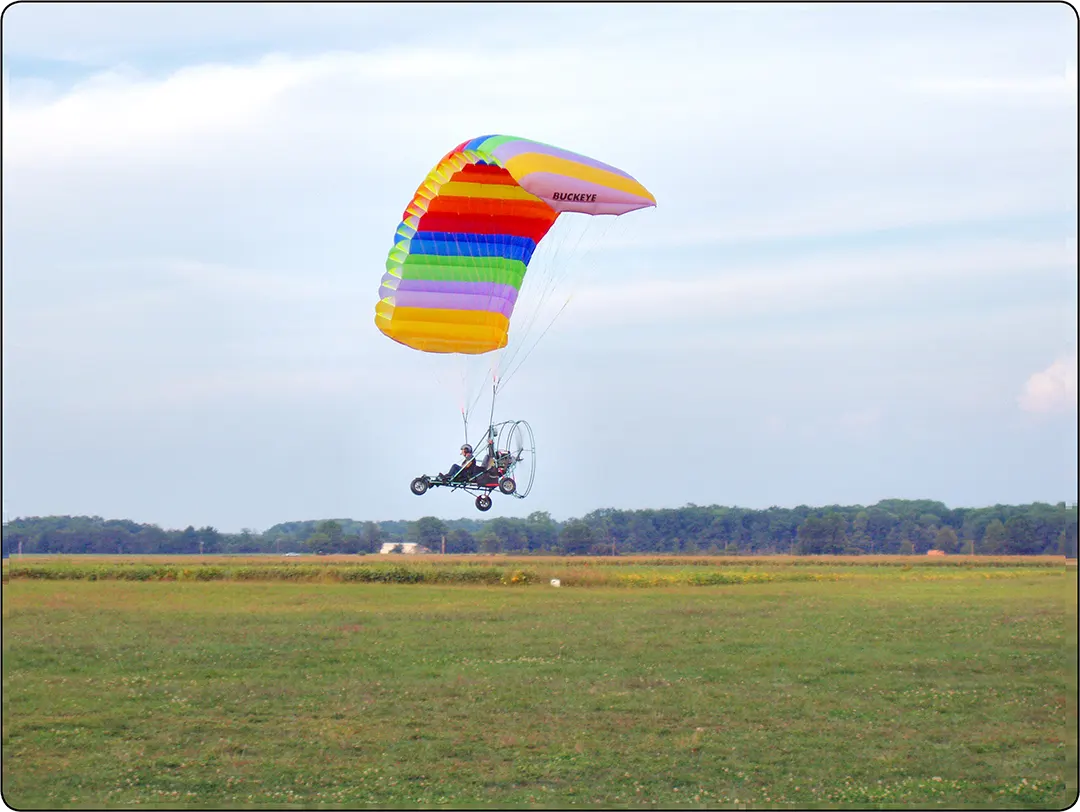
Powered Parachute Wing Construction
Each colored section of the inflated wing consists of cells that are open at the front to allow air to enter and closed at the rear to retain the air inside. Openings between the cells allow air to flow from one cell to another, helping equalize pressure throughout the inflated wing.
The wing is attached to the carriage by numerous nylon or Kevlar suspension lines. These lines extend from different locations along the wing toward the aircraft’s carriage. Their individual lengths and the weight of the aircraft acting through the lines help the inflated wing maintain its designed shape.
The suspension lines attach to the aircraft near the center of gravity. The attachment point can be adjusted to account for changes in balance caused by occupants of different weights.
Takeoff and Flight Characteristics
Like weight-shift control aircraft, powered parachutes do not use the traditional flight controls found on a fixed-wing airplane. When the wing is inflated and the aircraft begins moving forward, the wing produces lift.
As the aircraft accelerates, its airspeed increases and the wing produces more lift. When sufficient lift is produced to support the aircraft’s weight, the powered parachute lifts off the ground.
Unlike a conventional airplane, in which the pilot controls rotation using the elevator, a powered parachute generally lifts off when it reaches the required airspeed and lift condition.
The source describes a typical liftoff speed of approximately 28–30 mph and an in-flight airspeed of approximately 30 mph. These values are typical examples only and vary with aircraft model, wing, loading, and operating conditions.
Climb and Descent Control
Once the powered parachute is in flight, climbing and descending are primarily controlled by engine power.
Advancing the throttle increases engine power and generally causes the aircraft to climb, while reducing throttle power generally causes it to descend. The inflated wing produces considerable drag, so reducing engine power can result in a controllable descent.
The throttle used to control engine power is typically located on the right-hand side of the pilot. Figure 2 shows a two-seat powered parachute and its carriage structure.

Directional Control
Turning a powered parachute in flight is controlled by foot-operated pedals or steering bars located at the front of the aircraft. These controls are shown in Figure 2.
Each pedal operates a set of steering lines, usually made of nylon, that run upward to the trailing edge of the corresponding side of the wing.
When the right foot pedal is pushed, the steering line pulls down the trailing edge of the right side of the wing. This increases drag on the right side, causing the powered parachute to turn to the right.
When pressure is released from the pedal, the steering input is reduced and the wing returns toward its normal configuration. The aircraft then tends to resume its trimmed flight path, although the pilot may need to make additional corrections.
Landing a Powered Parachute
To land a powered parachute, the pilot reduces engine power and allows the aircraft to descend toward the landing area. With power reduced, the aircraft may descend at approximately 5–10 ft/s, although the actual descent rate depends on the aircraft and flight conditions.
As the aircraft approaches the ground, engine power may be increased as needed to help reduce the descent rate. Just before touchdown, the pilot applies input to both foot-operated steering controls, pulling down the trailing edges on both sides of the wing.
This action increases drag and changes the shape of the wing, increasing its angle of attack and lift while reducing forward speed. This technique is known as flaring and helps reduce the aircraft’s descent rate and forward speed during touchdown.
Figure 3 shows the pilot applying both foot controls, with the left and right wing trailing edges deflected downward.

When the aircraft touches down, the wing may trail behind the carriage as a result of the increased drag and altered aerodynamic forces. The flare helps reduce the descent rate and allows for a gentler landing.
The timing and amount of flare are important. If the pilot applies the steering controls too early or excessively, the wing may move too far aft, potentially resulting in an undesirable descent rate or a hard landing.
The appropriate control inputs depend on the powered parachute’s design, flight conditions, and manufacturer procedures.