The helicopter, as we know it today, belongs to a category of aircraft known as rotorcraft. Rotorcraft are also called rotary-wing aircraft because, instead of having fixed wings like an airplane, they use rotating wings to produce lift. The rotating rotor blades can be considered lift-producing surfaces, similar to the wings of an airplane, or thrust-producing devices, similar to the propeller on a piston-engine aircraft.
Helicopter aerodynamics involves the operation of the main rotor and tail rotor, the control of the helicopter around its three axes, and the aerodynamic effects that occur during hovering and forward flight. Understanding these principles is important for explaining how a helicopter can take off and land vertically, maneuver in different directions, and perform an autorotation landing following an engine failure.
Table of Contents
Table of Contents
Helicopter Structures and Airfoils
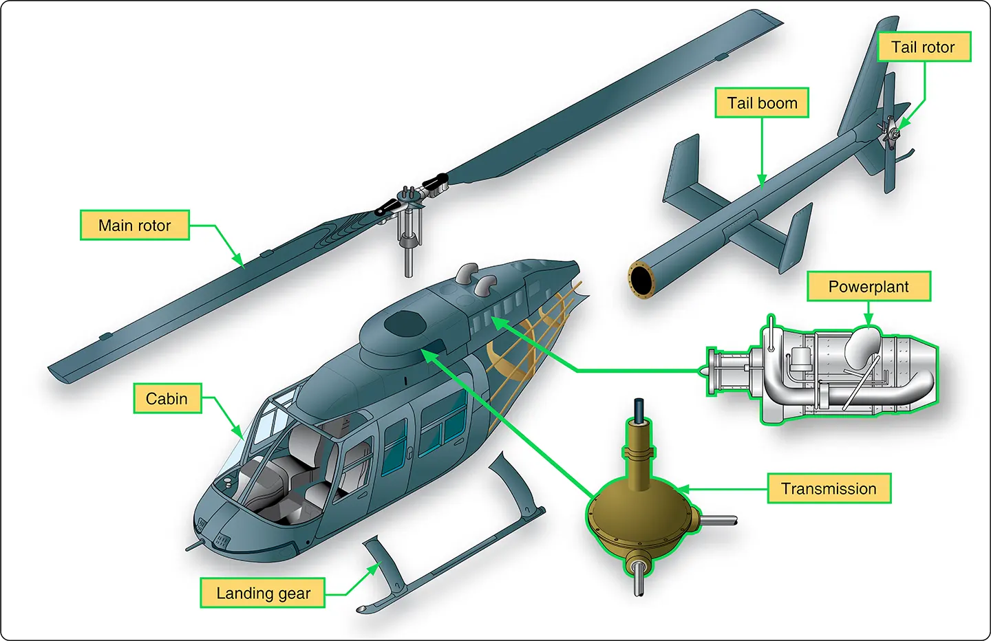
The main parts that make up a helicopter include the cabin, landing gear, tail boom, powerplant, transmission, main rotor, and tail rotor (Figure 1).
Main Rotor Systems
Helicopters use different main rotor systems. The three common types are fully articulated, semi-rigid, and rigid rotor systems.
Fully Articulated Rotor System
In a fully articulated rotor system, the blades are attached to the rotor hub through hinges that allow several types of movement. The blades can move up and down, move fore and aft, and rotate around their pitch-change axes.
Rotor systems using this arrangement typically have three or more blades.
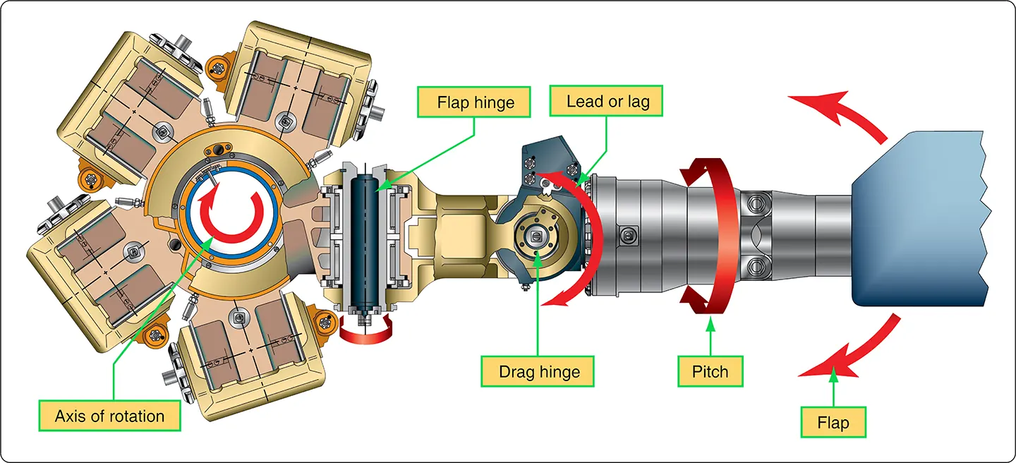
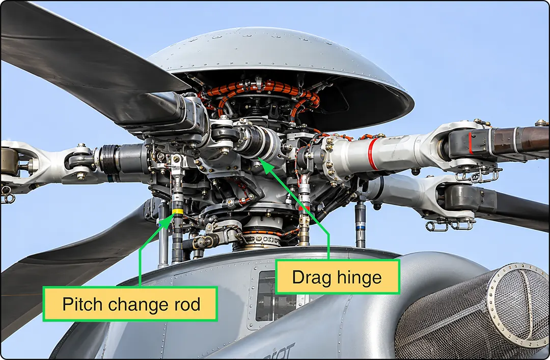
The hinge that allows the blades to move up and down is called the flap hinge, and movement around this hinge is called flapping. The hinge that allows the blades to move fore and aft is called the drag hinge or lag hinge. Movement around this hinge is called dragging, lead-lag, or hunting. The blades also rotate around their pitch-change axes to change blade pitch.
These hinges and their associated movements are shown in Figure 2. The main rotor head of a Eurocopter Model 725 is shown in Figure 3, with the drag hinge and pitch-change rods visible.
Semi-Rigid Rotor System
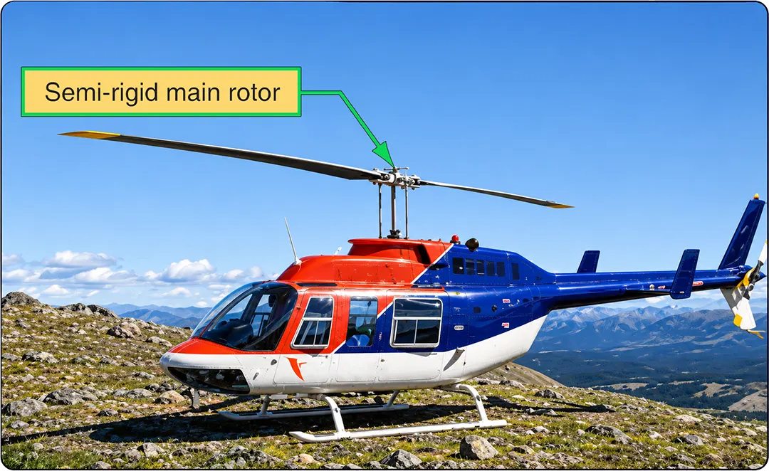
The semi-rigid rotor system is commonly used with a two-blade main rotor. The blades are attached to the hub so that the hub and blades can teeter like a seesaw. This teetering action allows one blade to move upward while the other moves downward.
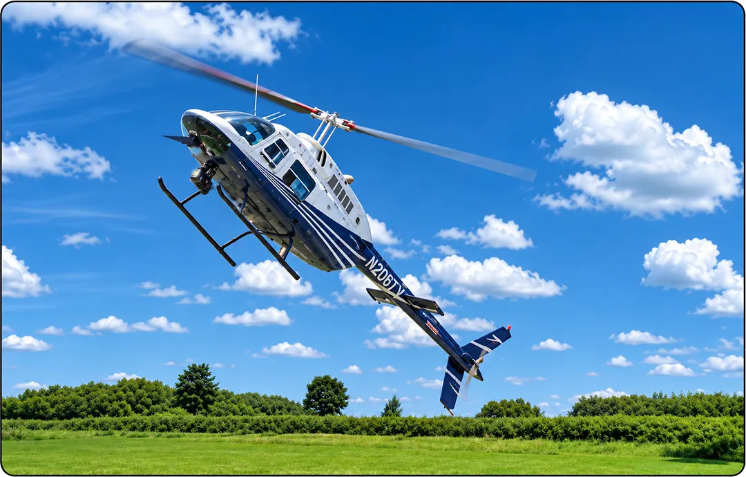
The blades also change pitch as the pilot operates the flight controls. Figure 4 shows a Bell Jet Ranger helicopter in flight. This helicopter uses a semi-rigid rotor system.
Rigid Rotor System
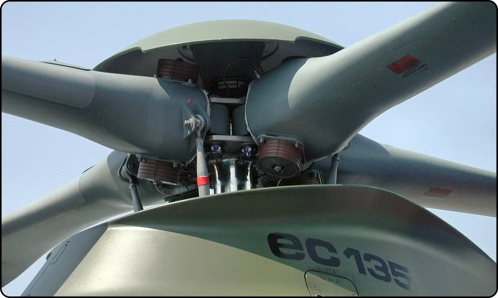
With a rigid rotor system, the blades do not use conventional flapping or lead-lag hinges. However, they can rotate around their pitch-change axes, allowing their blade angles to change.
Rigid rotor systems use blades and rotor components that are strong but also flexible enough to bend as necessary. This flexibility allows the blades to accommodate changes in lift during flight without requiring conventional flapping or lead-lag hinges or a teetering rotor arrangement.
The Eurocopter Model 135 uses a rigid rotor system (Figure 5).
Anti-Torque Systems
Whenever a helicopter’s main rotor is driven by the engine, an opposing reaction torque acts on the helicopter fuselage. For example, if the main rotor rotates clockwise when viewed from above, the fuselage tends to rotate counterclockwise. This reaction is a result of the torque applied to the rotor system.
In the Force, Work, Power, and Torque section, torque was discussed as the turning effect of a force. A helicopter therefore requires an anti-torque system to counteract the reaction torque produced by the main rotor.
Tail Rotor
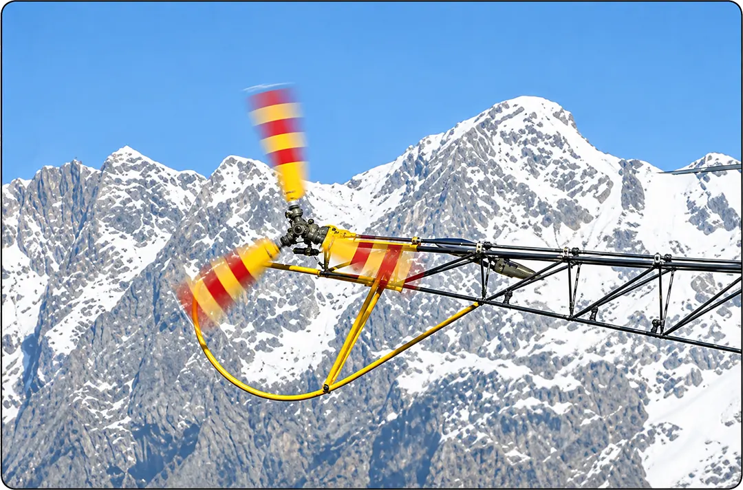
One common method of counteracting main rotor torque is to place a smaller set of rotating blades at the end of the tail boom. These blades are called the tail rotor or anti-torque rotor. Their purpose is to produce thrust that creates a moment opposite to the main rotor’s reaction torque.
The torque produced by the tail rotor depends on its thrust and the distance from the main rotor axis to the tail rotor. The tail rotor thrust, measured in pounds, multiplied by this distance, measured in feet, produces a torque measured in pound-feet.
Figure 6 shows a three-bladed tail rotor on an Aerospatiale AS-315B helicopter. This tail rotor has open-tipped, variable-pitch blades. The helicopter’s anti-torque pedals, which are positioned like the rudder pedals in an airplane, control the blade pitch and therefore the amount of thrust produced.
Some potential disadvantages of a conventional tail rotor system are:
- The rotating blades can be hazardous to personnel who approach the helicopter on the ground.
- During forward flight, a vertical fin may help provide directional stability and reduce the anti-torque thrust required. However, the tail rotor still consumes engine power and produces drag.
Fenestron
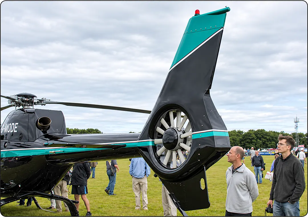
An alternative to the conventional tail rotor shown in Figure 6 is an anti-torque system known as a fenestron, or fan-in-tail design. This system uses multiple rotating blades enclosed within a circular shroud at the end of the tail boom.
The shroud helps protect personnel from direct contact with the rotating blades. It can also reduce certain forms of tail-rotor noise and improve safety around the helicopter. A fenestron system is shown in Figure 7.
NOTAR System
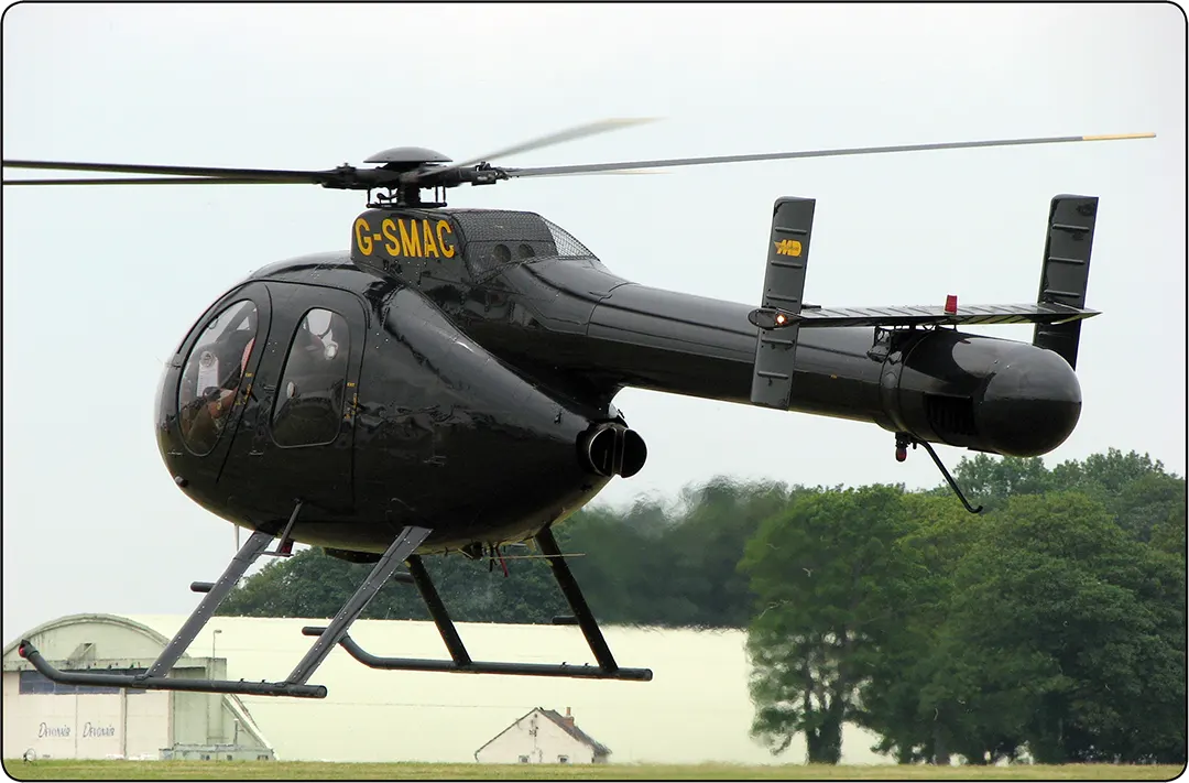
A third method of counteracting the torque of a helicopter’s main rotor is a technique called the No Tail Rotor (NOTAR) system.
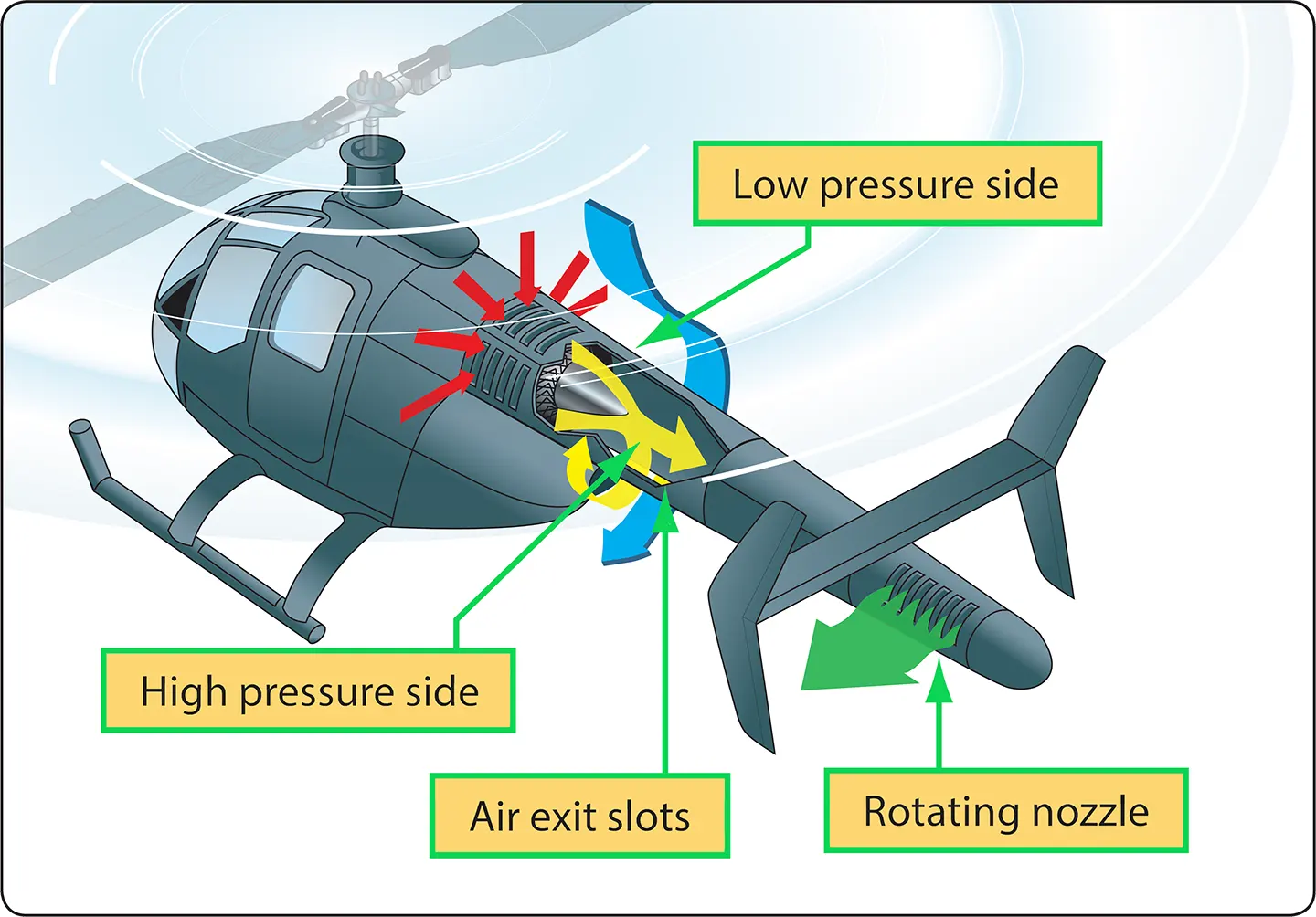
This system uses a fan driven by the helicopter’s engine to produce a high volume of low-pressure air. The fan forces air into the tail boom. A portion of this air exits through slots on the right side of the boom. The airflow, together with the main rotor downwash, produces a phenomenon known as the Coandă effect.
The airflow from the slots helps create a pressure difference around the tail boom. This produces a side force that contributes to counteracting the torque of the main rotor.
The remainder of the air travels to a controllable rotating nozzle at the rear of the helicopter. Air exits the nozzle at high velocity, creating additional thrust that helps counteract main rotor torque and provides directional control.
A NOTAR system is shown in Figures 8 and 9.
Counter-Rotating Main Rotors
Some helicopters have two main rotors, such as the Chinook, which has one main rotor at each end of the fuselage. These helicopters do not require a conventional tail rotor to counteract main rotor torque.
The two main rotors rotate in opposite directions. Their reaction torques oppose one another and are designed to cancel out, eliminating the need for a separate anti-torque rotor.
Helicopter Axes of Flight
Helicopters, like airplanes, have three axes: vertical, lateral, and longitudinal. These axes pass through the helicopter’s center of gravity (CG).
A helicopter yaws around the vertical axis, pitches around the lateral axis, and rolls around the longitudinal axis. Figure 10 shows the three axes of a helicopter and how they relate to its movement.
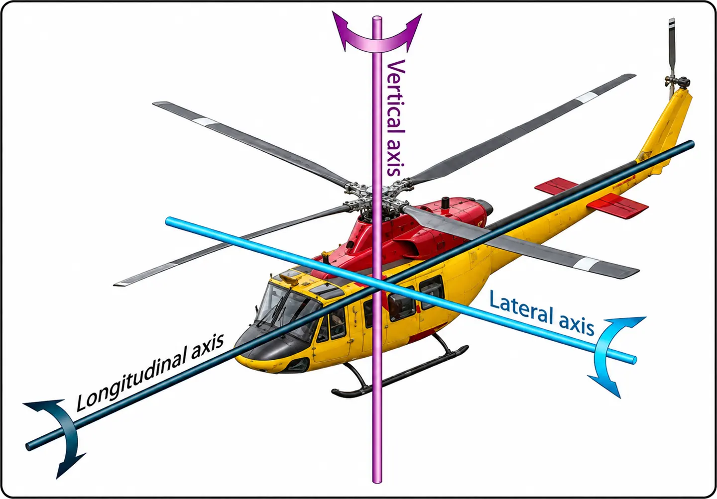
All three axes intersect at the helicopter’s center of gravity, around which the helicopter rotates. The position of the center of gravity relative to the main rotor system is important because the helicopter must remain within its approved weight-and-balance limits.
Control Around the Vertical Axis
For a single-main-rotor helicopter, control around the vertical axis is handled by the anti-torque system. This may be a conventional tail rotor, a fenestron, or the airflow from the fan and controllable nozzle of a NOTAR system.
As in an airplane, rotation around the vertical axis is known as yaw. The pilot controls yaw by pushing the anti-torque pedals located on the cockpit floor, in a manner similar to using the rudder pedals in an airplane.
To make the nose of the helicopter yaw to the right, the pilot pushes the right anti-torque pedal. For a helicopter whose main rotor tends to rotate the fuselage counterclockwise when viewed from above, the tail rotor must produce a force that counters this reaction torque. The required pedal input depends on the direction of the main rotor’s rotation and the helicopter’s design.
By using the anti-torque pedals, the pilot can intentionally make the helicopter rotate in either direction around the vertical axis. The anti-torque pedals can be seen in Figure 11.
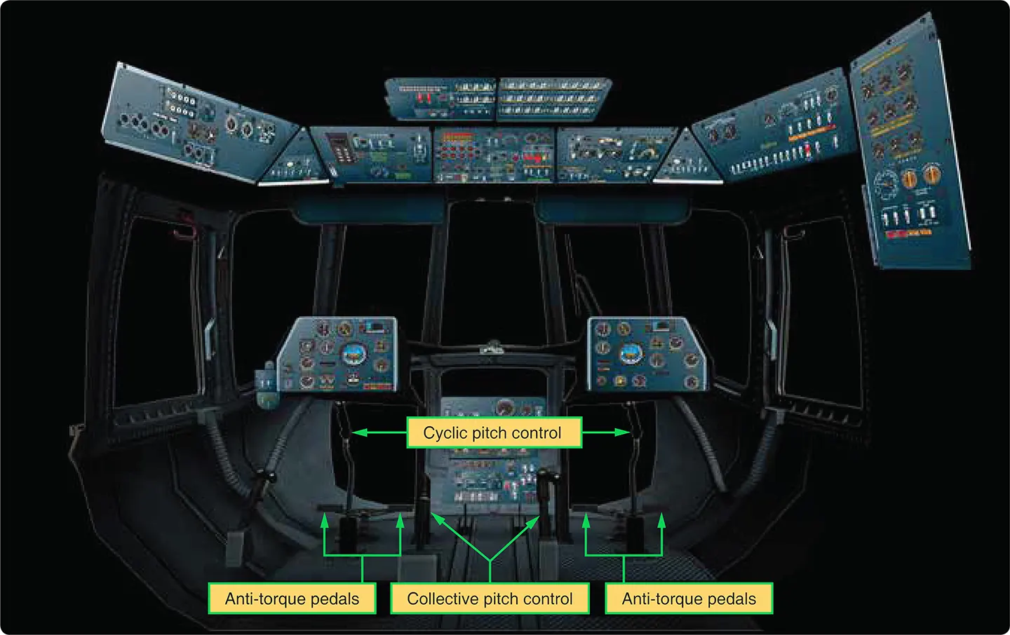
Some helicopters have a vertical stabilizer, such as those shown in Figures 10 and 12. During forward flight, the vertical stabilizer produces an aerodynamic force that helps counteract the main rotor’s torque. This reduces the amount of thrust required from the anti-torque system.
Control Around the Longitudinal and Lateral Axes
Movement around the longitudinal and lateral axes is controlled by the helicopter’s main rotor. In the cockpit, the pilot uses two primary controls for this purpose: the collective pitch control and the cyclic pitch control.
The collective pitch lever is located beside the pilot’s seat, while the cyclic pitch control is positioned in front of the seat (Figure 11).
Collective Pitch Control
When the collective pitch control lever is raised, the pitch angle of all the main rotor blades increases by approximately the same amount. This increases the total lift produced by the rotor system and allows the helicopter to climb vertically when the lift exceeds its weight.
The engine must also produce enough power to drive the main rotor and the anti-torque system. The grip at the end of the collective control may include a throttle that the pilot can rotate to increase engine power. On many helicopters, an engine governor or control system automatically adjusts engine power as the collective pitch is increased.
The collective pitch lever may have adjustable friction so that the pilot does not have to maintain constant upward pressure on it during flight.
Cyclic Pitch Control
The cyclic pitch control lever, like the control yoke of an airplane, can be pulled back, pushed forward, or moved left and right. It changes the pitch of each rotor blade cyclically as the blade rotates around the rotor disc. This changes the distribution of lift around the rotor disc and causes the rotor disc to tilt.
When the cyclic pitch lever is pushed forward, the rotor system is commanded to tilt forward. The cyclic pitch mechanism changes the blade pitch at different positions around the rotor disc, producing the required aerodynamic forces and flapping response. The resulting forward tilt of the rotor thrust causes the helicopter to accelerate forward.
The pitch-change rods are part of the mechanism that changes the pitch of the rotor blades in response to cyclic control inputs.
When the cyclic pitch lever is pulled back, the rotor disc tilts rearward and the helicopter can move backward.
If the cyclic pitch lever is moved to the left or right, the helicopter banks in the corresponding direction. For the helicopter to bank to the right, the rotor system is commanded to tilt to the right. The cyclic pitch mechanism changes the blade pitch around the rotor disc to produce the required rolling moment.
By tilting the rotor disc forward and to the right, for example, the helicopter can move forward while banking to the right. In Figure 12, an Agusta A-109 can be seen in forward flight and banking to the right. The rotor blades shown in the rear and on the left side are raised, demonstrating the blade-flapping movement.
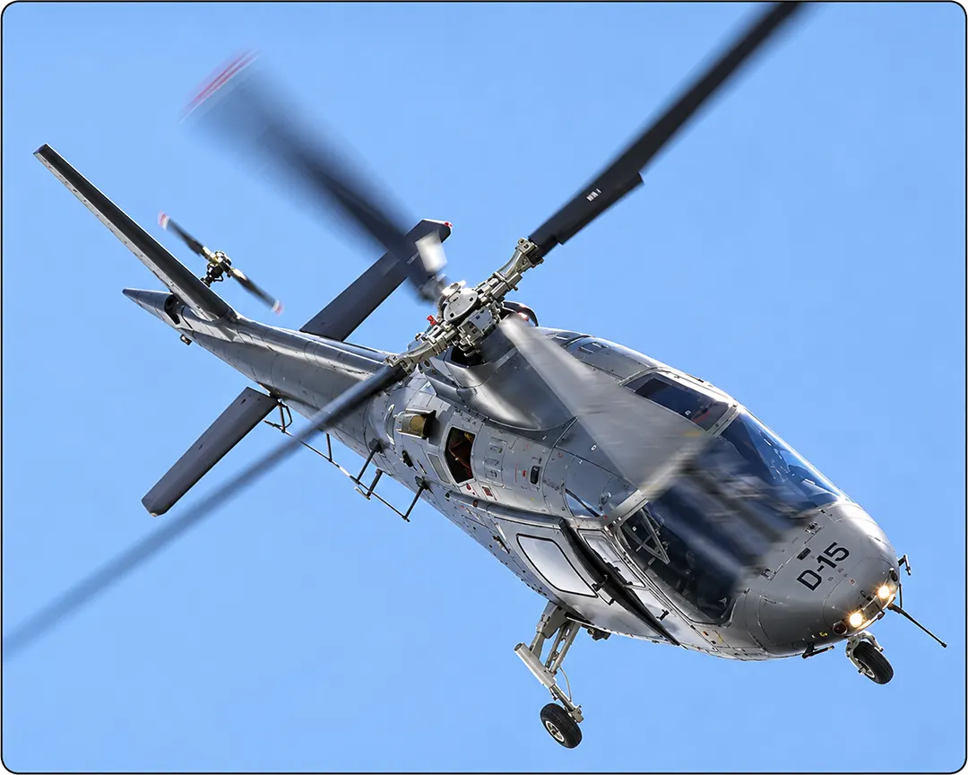
Some helicopters use a horizontal stabilizer, similar to the one found on an airplane, to provide additional stability around the lateral axis. A horizontal stabilizer can be seen on the Agusta A-109 in Figure 12.
Helicopters in Flight
Hovering
For a helicopter, hovering means maintaining flight at a constant altitude without forward, backward, or sideways movement relative to the surrounding air.
To hover steadily, the main rotor must produce enough lift to equal the helicopter’s weight. The engine must also produce enough power to drive the main rotor and the anti-torque system.
The ability of a helicopter to hover is affected by several factors, including whether it is operating in ground effect, the density altitude of the air, the power available from the engine, and the helicopter’s gross weight.
Ground Effect
A helicopter experiences ground effect when it hovers close to the ground. As a general approximation, ground effect is significant when the helicopter is within about one-half of the main rotor diameter above the surface.
For example, if a helicopter has a main rotor diameter of 40 ft, ground effect may be significant at an altitude of approximately 20 ft or less above the ground.
When the helicopter is close to the ground, the ground interferes with the rotor downwash and reduces the induced airflow through the rotor system. This reduces induced power requirements and allows the helicopter to hover more efficiently.
As a result, a helicopter can generally hover at a higher gross weight in ground effect than it can out of ground effect, assuming other conditions remain the same.
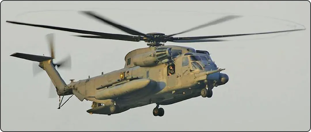
The strength of the ground-effect benefit depends on factors such as rotor height, rotor diameter, surface conditions, wind, and the helicopter’s operating condition. In Figure 13, an Air Force CH-53 is shown hovering, with the rotor blades flapping upward as a result of the aerodynamic forces acting on them.
Forward Flight
In the early days of helicopter development, the ability to hover was mastered before successful forward flight was achieved. Early attempts at forward flight encountered a problem that caused helicopters to roll as they began moving away from a hover. This problem is known as dissymmetry of lift.
When a helicopter is hovering, the rotor blades experience approximately the same airflow velocity around the rotor disc, assuming steady conditions. When the helicopter begins moving forward, the airflow experienced by each blade changes.
For helicopters with a main rotor that turns counterclockwise when viewed from above, the blades moving around the right side of the helicopter are moving toward the nose, while the blades moving around the left side are moving toward the tail.
When the helicopter begins moving forward, the blade on the right side moves toward the relative wind and is known as the advancing blade. The blade on the left side moves away from the relative wind and is known as the retreating blade.
The advancing blade experiences a higher relative airflow velocity and tends to produce more lift. The retreating blade experiences a lower relative airflow velocity and tends to produce less lift. This difference in lift is called dissymmetry of lift. Figure 14 shows how this occurs.
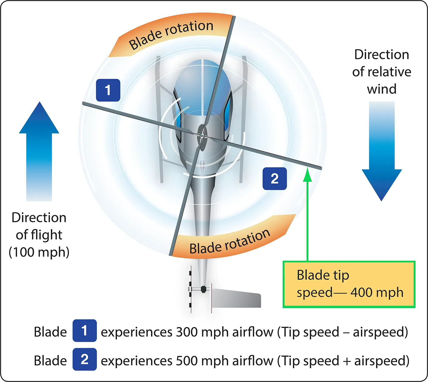
In Figure 14, blade number 2 is identified as the advancing blade, and blade number 1 is identified as the retreating blade. The increased lift on the advancing side and the reduced lift on the retreating side create a rolling tendency that must be corrected by the rotor system.
Blade Flapping
To compensate for dissymmetry of lift, helicopter rotor systems use blade flapping and cyclic pitch control. These actions help maintain a more balanced lift distribution across the rotor disc.
When an advancing blade experiences increased airflow velocity and lift, it tends to flap upward. As the blade moves upward, the direction of the relative airflow changes in relation to its chord line. This reduces the blade’s effective angle of attack and helps reduce its lift.
The retreating blade experiences reduced airflow velocity and lift, causing it to flap downward. As it flaps downward, its effective angle of attack increases, helping restore lift.
The combined flapping and cyclic pitch responses help compensate for the lift difference between the advancing and retreating blades and reduce the tendency for the helicopter to roll.
The semi-rigid and fully articulated rotor systems use flapping hinges or a teetering arrangement to allow the blades to move up or down as lift changes. A rigid rotor system uses the flexibility of its blades and other rotor components to accommodate these movements.
Advancing-Blade and Retreating-Blade Problems
As a helicopter’s forward speed increases, the advancing blade experiences increasingly high relative airflow velocity. At sufficiently high speeds, the airflow over the advancing blade may approach the speed of sound. Compressibility effects can then become significant, and shock waves and airflow separation may develop. These effects can cause high drag, vibration, and limitations on the helicopter’s maximum forward speed.
The retreating blade experiences decreasing relative airflow velocity as the helicopter’s forward speed increases. To compensate for the reduced airflow velocity and maintain lift, the retreating blade must operate at a higher angle of attack.
At sufficiently high forward speeds, the retreating blade may reach its critical angle of attack and stall. This condition is known as retreating-blade stall. The stall often begins near the blade tip and progresses inward toward the blade root.
The combination of advancing-blade compressibility effects and retreating-blade stall limits the maximum forward speed of a helicopter.
Conditions that can contribute to retreating-blade stall or reduce the helicopter’s available operating margin include:
- High forward speed
- Heavy gross weight
- Turbulent air
- High-density altitude
- Steep or abrupt turns
The actual operating limits depend on the helicopter’s design and flight conditions. Pilots must observe the limitations and procedures specified in the aircraft flight manual.
Autorotation
The engine of a helicopter drives the main rotor system through a transmission and a freewheeling unit. The freewheeling unit allows the engine and rotor system to operate independently when necessary. If the engine fails in flight, it allows the main rotor to continue rotating without being driven by the engine. This is essential for a flight condition called autorotation.
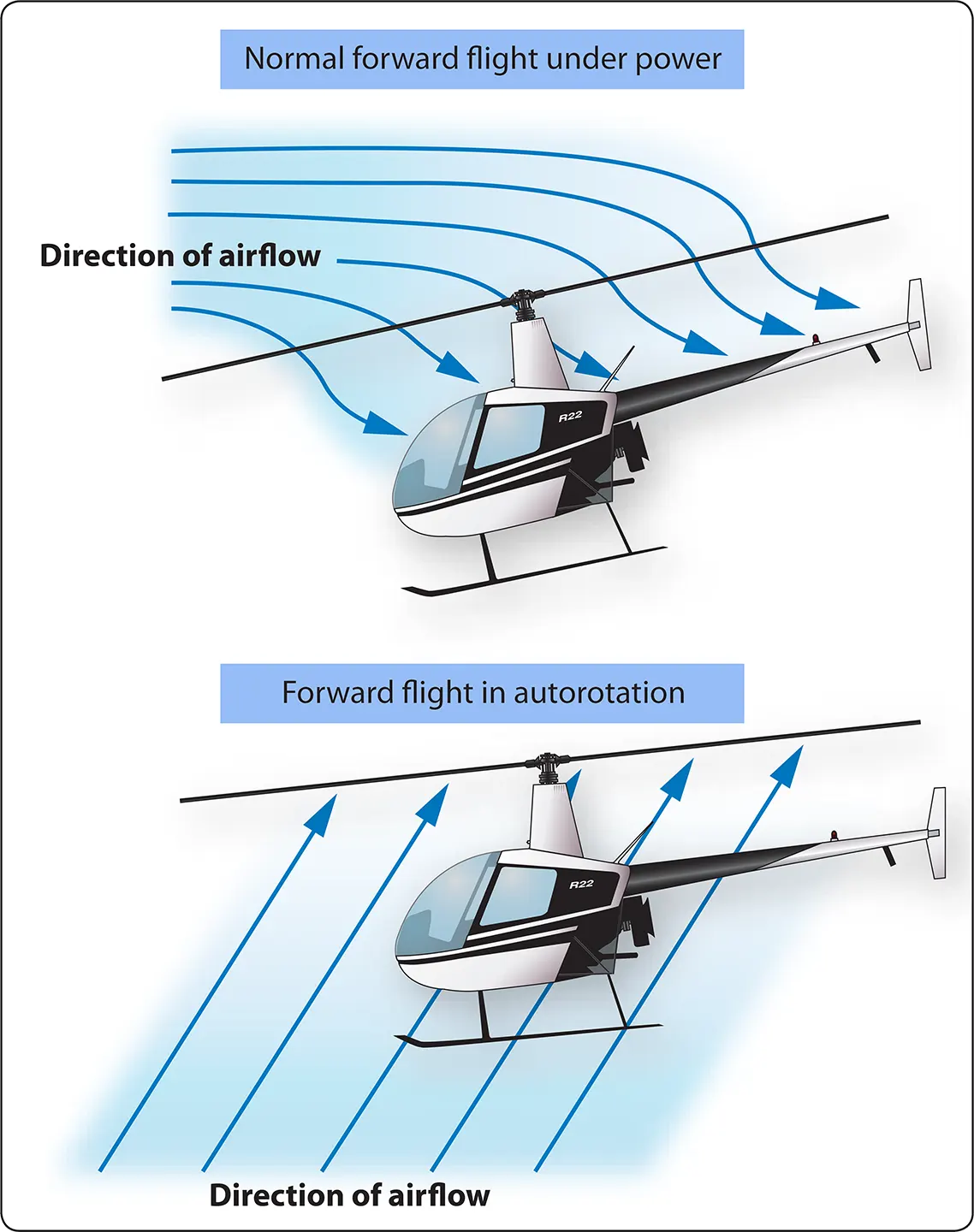
Autorotation is a flight condition in which the main rotor blades are driven by the airflow passing upward through the rotor system rather than by engine power. This condition is somewhat similar to an airplane gliding after an engine failure.
During autorotation, the pilot lowers the collective pitch to reduce blade pitch and maintain rotor RPM. As the helicopter descends, air flows upward through the rotor disc and provides the aerodynamic force needed to keep the rotor turning.
The helicopter gives up altitude, which represents potential energy, while the rotor system maintains rotational energy. The pilot must manage rotor RPM, airspeed, and descent rate throughout the maneuver.
As the helicopter approaches the ground, the pilot uses the cyclic pitch control to reduce forward speed and flare the helicopter. During the final stage of the landing, the collective pitch control is raised to increase rotor lift and cushion the touchdown.
The airflow through the rotor blades during normal forward flight and during an autorotation flight condition is shown in Figure 15. In Figure 16, a Bell Jet Ranger is shown approaching the ground during the final stage of an autorotation.